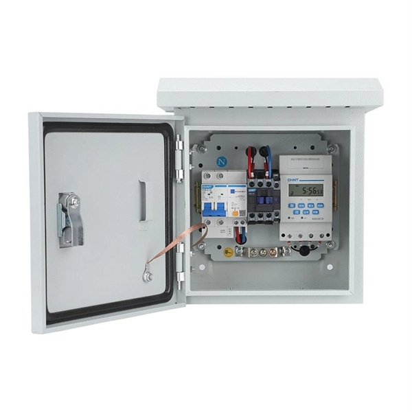
Follow a step-by-step process: mark the location, drill holes, insert anchors, and secure the box for a weatherproof fit. Apply weatherproof sealant around the box edges and cable entry points to prevent water ingress. Installing an electrical box on an exterior wall can seem daunting, but with the right guidance, it can be a straightforward task. Whether you are adding an outdoor outlet for convenience or setting up lighting, understanding the process is key. This guide will walk you through the essentials of. An electrical junction box is a protective housing designed to enclose and shield electrical wire connections or splices. For outdoor installations, the box must defend these sensitive splices against moisture, dust, temperature fluctuations, and physical impacts. Safety remains crucial during installation. It takes the incoming power and safely distributes it to different circuits throughout your building. Whether in a home or an industrial facility, this box keeps your electrical setup organized, functional, and efficient. Whether adding a GFCI outlet for safety or upgrading an exterior outlet for weather-resistant durability, it's essential to follow proper electrical wiring. In this video, I'll show you how to install a weatherproof outdoor electrical box — safe, secure, and code-compliant.
[PDF]
Electricity is delivered at a frequency of either 50 or 60 Hz, depending on the region. It is delivered to domestic customers as. In some countries as in Europe a supply may be made available for larger properties. Seen with an, the domestic power supply in North America would look like a, oscillating between −170 volts and 170 volts, giving an effective voltage of 12.
[PDF]
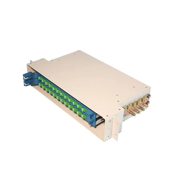
They come in a range of sizes, and are typically mountable, whether that's on a wall, or on a rack to make for easier cable and port management. Patch panels are a great way to improve your network management by making it simple to organize your cables and connections. In this case, we will be talking about a very versatile type of patch panel known as a shielded wall mounted patch panel. Patch panels even let you. When building or upgrading a fiber network, choosing between rack-mount and wall-mount patch panels can have a big impact on performance, organization, and scalability. The difference lies in where and how they fit into your setup. Check each product page for other buying options. Need help? Streamline your cabling with wall-mounted patch panels. Discover compact, space-saving options featuring sturdy metal construction and flexible installation. Among the various FDU types—including fiber distribution boxes, termination units, rackmount patch panels, and outdoor-rated enclosures—wall mount fiber patch panels stand out for their space-efficient design and versatile applications. Whether you're setting up a home office network, a small data. Pick wall mount patch panels for small networks. They are more organized and can expand easily.
[PDF]

Built on Huawei's unified software platform and equipped with high-performance fully programmable chips, they deliver abundant features including Service Roam, VXLAN and iFlow, helping customers build high-quality campus bearing networks for the all-wireless era. Leveraging the Service. CloudEngine S5735-S-V2 switches support simplified operations and maintenance (O&M), and flexible Ethernet networking. It also provides enhanced Layer 3 features and mature IPv6 features. For example, it can be used as an access or. CloudEngine S5736-S series switches are next-generation standard all-optical GE access switches that provide 24-port and 48-port models, and provide four 10GE ports and one extended slot(optional). CloudEngine S5736-S series all-optical GE access switches are developed based on next-generation. Comprehensive analysis of Huawei's revolutionary optical switch innovations for 2025, including data center all-optical switching, silicon photonics integration, quantum-compatible switches, and 5G-Advanced network solutions. The port supports the PoE function. It sends and receives service data at 1000 Mbit/s or 10 Gbit/s.
[PDF]

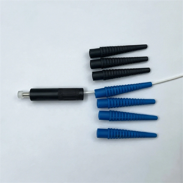
Learn how to monitor SFP optical power on Cisco switches, interpret Tx/Rx levels, and troubleshoot fiber link issues. Step-by-step CLI commands, model-specific guidance, and best practices included. In this article, we will break down the key factors influencing TX/RX power, explain how to calculate the optical power budget, and provide actionable insights for optimizing your network's performance using SFP modules. SFP (Small Form-Factor Pluggable) modules are compact transceivers that allow. SFP (Small Form-factor Pluggable) optical modules are compact, hot-pluggable transceivers that enable network equipment to connect seamlessly to fiber and copper links. Even if an interface appears up, degraded Tx/Rx levels can cause intermittent flapping, packet loss, or err-disabled states. Think of it as the “translator” for your network equipment, converting electrical signals into optical signals. The most two important factors of the SFP transceiver: Output power (TX power) and receiver sensitivity (RX sensitivity). The optical TX power is the signal level leaving from that device, which should be within the transmitter power range. The RX sensitivity is the incoming signal level being. In current network communication, SFP optical modules are an indispensable physical foundation for building network channels. They form high-speed channels for optical signal transmission. Therefore, to ensure their.
[PDF]
Silicon photonics is transforming AI computing by enabling energy-efficient, high-speed data transmission. Discover how optical interconnects present a possible solution to the data center energy crisis and drive sustainable innovation. Lam Research is setting the agenda for the wafer fabrication equipment industry's approach to a silicon photonics revolution, driving the breakthroughs in Specialty Technologies that will enable sustainable AI scaling through precision optical manufacturing. The artificial intelligence boom has. y with vastly reduced energy con-sumption by integrating optics deeply within computing sockets. We present the design and characterization of a dense wavelength-division multiplexing (DWDM) SiPh transceiver chip, featuring a unique architecture in the multi-FSR regime and targeting a shoreline. Silicon photonics is becoming a critical enabler of AI and HPC, breaking the limits of electrical interconnects in bandwidth, distance and power efficiency. Co-packaged optics (CPO) builds on silicon photonics, with SiPh transceivers as the integration platform and CPO as the packaging architecture. Silicon Photonics emerges as the solution to this predicament, replacing electrons with photons—the fundamental particles of light—to race across familiar silicon-based chips, promising a revolution in computing and communication. This isn't just about increased speed; it's about a profound impact.
[PDF]

Select the correct wavelength and set your reference. You measure optical power in dBm or insertion loss in dB. Consistent procedures ensure accuracy. Measure total signal loss from fiber, connectors, or splices. Optical fiber attenuation is the attenuation per unit length of optical fiber, and the unit is dB/km. When connecting two optical fibers, there will be loss inside any connector or joint. Consistent measurement techniques. While optical power meters are the primary power measurement instrument, optical loss test sets (OLTSs) and optical time domain reflectometers (OTDRs) also measure power in testing loss. TIA standard test FOTP-95 covers the measurement of optical power. Optical power is based on the heating power. Light Source: The CMA5 Series Light Sources provide an economical and stable laser source for use in point-to-point attenuation measurement. They feature a rugged design, built to withstand the difficult testing environment of fiber optic cable installation and maintenance. The CMA5 Light Sources. When talking about optical measurements, wavelength basically means how far a wave pattern repeats itself, usually measured in nanometers (nm). Commonly, a power meter on its own is used to measure absolute.
[PDF]
Whether you're building a commercial setup or upgrading an industrial plant, proper cable tray installation ensures neat wiring, safe access, and easy maintenance. But before you lay the first tray or clamp down a single cable, you need a solid plan. This guide breaks. This method statement covers the site installation of the cable tray & ladders and the requirements of checks to be carried out. The Cable Tray system is installed in electrical rooms, plant rooms, and service corridors. This guide breaks down the process step by step. This process is integral to determining the optimal arrangement and configuration of cable trays, which are essential for routing and supporting electrical cables within buildings and. 1. 0 This method statement will serve as a minimum guideline to carry out the Cable Tray Installation activities for commercial buildings, plants and refineries in accordance with Project Drawings and Specifications. This document outlines the key requirements for cable tray layout, installation, and fireproofing in industrial and commercial environments. Route. Below is the detailed cable tray installation method statement not only for cable tray but also applicable for GI ladder and trunking for indoor and outdoor applications and in service rooms like pump rooms, electrical rooms and plant rooms etc. All materials intended for cable tray, ladder and.
[PDF]

In today's video, we'll be unboxing the 9-Port Power Supply Box and demonstrating how to connect the cables to provide power to CCTV cameras. A CCTV power supply box sends power to all your cameras from one place. It helps keep things neat and makes your system easier to manage. In this guide, you'll learn how to install it step by step, choose the right type, avoid common problems, and keep your system running safely. Power supply boxes for CCTV are typically used in multi-camera installations instead of using single power adapters for each camera. The process is almost exactly the same if you. Installers of surveillance systems may simply control the power to various CCTV cameras using a CCTV power supply box, also known as a power distribution box (usually at the location of the DVR). This enables a cleaner camera installation. Surge protection can be accomplished in two ways. The power supply box is specifically used to transfer power requirements for all cameras plugged in on the system, to work. Security cameras use RG59U coax siamese wire or CAT5e networking cable to transmit video. Whether you are installing a power box for a new or existing camera system, it is important to understand how to connect cameras to a CCTV Power Supply Box. DC current is polarized meaning it has two leads, a.
[PDF]
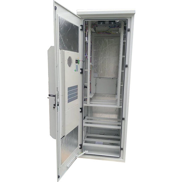
In this guide, we'll break down everything you need to know to install a distribution box correctly and confidently. Choose the right box based on environment (indoor/outdoor), load capacity, and durability. Check for proper IP/NEMA ratings and material quality. This section includes guidelines for the construction, installation, and inspection of electrical systems. Review Part 4, “Highway Traffic Signals,” of the California Manual on Uniform Traffic Control Devices; California Code of Regulations, Title 8, “Electrical Safety Orders,” (8 CCR 2299 et. The QUAZITE® H20 enclosures include a rugged polymer concrete box with a galvanized steel frame and cover surrounded by a minimum of 3 inches of cast-in-place concrete. For scenarios that could benefit from this type of enclosure, read our blog. When is a roadway like a bridge? Any underground. Learn how to wire a distribution box step by step! This video shows real on-site footage of electrical installation, demonstrating safe and standardized wiring methods used by professionals. Covers wiring, placement, standards, and expert tips for a compliant setup. It takes the incoming power and safely distributes it to different circuits throughout your building. the shoulder surface. Restore the disturbed area around the pull box and m cover of 12 inches. Otherwise, provide a minim.
[PDF]
Fault Detection: Quickly identifies and isolates faults in the power system. Feeder Switching: Automatically switches power routes to maintain supply during faults. Outage Management: Reduces downtime by quickly restoring power. Voltage Control: Maintains stable voltage levels in the network. One key solution to this challenge is the adoption of distribution automation (DA) systems, which offer benefits including improved system reliability, enhanced crew safety and reduced outage durations. power distribution systems had adopted automated switching by the. This White Paper, “Smart Grid for Distribution Systems” addresses the benefits and challenges of implementing the many different Distribution Automation functions. Distribution systems have traditionally not involved much automation. Distribution equipment, once installed on feeders, was expected. Power Distribution Automation (PDA) involves the use of advanced technologies to enhance the efficiency, reliability, and safety of electrical power distribution networks. With automation.
[PDF]

Traditional pluggable optical modules are approaching their physical limits in three core dimensions: power consumption control, signal integrity and port bandwidth density. Low Latency: LPO technology eliminates the need for a DSP, reducing a processing step and thus lowering data transmission latency. This advantage is particularly important in high-performance computing (HPC) scenarios, where minimizing latency is a key factor in achieving optimal performance. By. Among the emerging technologies, LPO (Linear Pluggable Optics), NPO (Near-Packaged Optics), and CPO (Co-Packaged Optics) represent three important stages in the evolution of next-generation data center optical networking. Understanding how these architectures differ is essential for designing. Optical communications are emerging as the next AI computing infrastructure frontier, driven by data interconnection bottlenecks. Lumentum's order book is full through 2028, reflecting surging demand for 800G and 1. 6T optical modules, amplified by Nvidia's strategic investment., May 4, 2026 – GlobalFoundries (Nasdaq: GFS) (GF) today announced the introduction of its SCALE™ optical module solution for co-packaged optics (CPO). GF's SCALE. In Feb. 2023, the State Council issued the "Overall Layout Plan for Digital China Construction. ” It proposes six key tasks,including enhancing the efficient.
[PDF]
Electric power distribution systems are designed to serve their customers with reliable and high-quality power. The most common distribution system consists of simple radial circuits (feeders) that can be ove.
[PDF]

While optical power meters are the primary power measurement instrument, optical loss test sets (OLTSs) and optical time domain reflectometers (OTDRs) also measure power in testing loss. TIA standard test FOTP-95 covers the measurement of optical power. This measurement is the basis for loss measurements as well as the power from a source or presented at a receiver. Typically both transmitters and receivers have receptacles for fiber optic connectors, so measuring the. You need a power meter to measure power in a fiber optic system; most power meters come with a screw-on-adapter that matches the connector being tested and a little aid from the network electronics to turn on the transmitter. During the measurement of power, the meter must be set to the proper. Fluke Networks sets the standard in network testing with its advanced range of fiber optic power meters and fault locators, designed to ensure the highest precision in fiber optic meter readings and power evaluations. This is measured in decibels (dB). Splitters, fusion splices, connectors and. To use a power meter for fiber optic testing, always clean connectors first with lint-free wipes or click-to-clean tools. Select the correct wavelength and set your reference. Consistent procedures ensure accuracy.
[PDF]

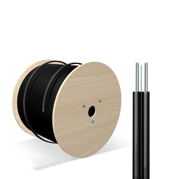
Optical fibers or fiber cables can be used for transmitting optical power from a source to some application. In their served areas will be power generating stations, alternative energy sources (solar, wind, geotherman, etc. ), substations for distribution and microgrids. These networks must be monitored and managed to ensure reliable power for the utility's customers. For monitoring and managing networks. Low voltage cables are mounted on poles in the "telecom space," well below power cables. Optical power ground wire (OPGW) is an electrical power ground with fiber optics in the center of the conductor. That conversion can be done with a photovoltaic cell. The Commission, on June 22, 1965, noting that the increasing demand for underground electric and communication facilities in California has brought about substantial increases in the construction of such facilities, and that it appeared it may be desirable, pursuant to Sections 761, 768 and 8056 of. One choice is optical power ground wire (OPGW). This conductive cable is run at the top of the tower or pole to be the ground conductor and protect the power cables from lightning. The fiber. While fiber optics is essential for internet service providers to deliver higher bandwidth and faster transmit speeds, there are also many crucial benefits of fiber optics in energy and power. Utility companies face various challenges as they work to deliver reliable energy to homes and industries.
[PDF]