In this comprehensive guide, we'll walk through the best practices for installing various types of fiber optic cable, from patch cords to distribution fiber, and provide practical tips to ensure a successful installation. Correct patch-cord installation is essential for maintaining low insertion loss, stable return loss, and long-term reliability in both indoor and outdoor fiber networks. Proper handling, routing, cleaning, bend-radius management, and connector alignment ensure that the optical link meets design. Proper installation and regular maintenance of fiber optic patch cords play a crucial role in achieving optimized network performance, preventing signal errors, and extending service life. This guide addresses expert-certified best practices applied by professionals in the telecommunications, data. Proper connection of fiber optic cables is essential to harness these benefits fully, as even minor errors can lead to significant performance issues like signal loss. Whether you're connecting a data center, a corporate network, or a high-density fiber infrastructure, correct installation methods are essential. Yingda. In today's high-performance networks, fiber optic patch cables are the lifelines that ensure smooth data flow across switches, servers, and routers. Even the most advanced optical transceivers can only perform at their peak when paired with properly installed, clean, and precisely managed fiber.
[PDF]
* Bronze alloy bolts shall have a minimum tensile strength of 70,000 pounds per square inch. ** Bolts, cap screws, nuts, flat washers, locknuts: 18-8 alloy. Qualified to meet or exceed all the nationally recognized standards, including ANSI C119. 4 and NEMA CC1, the DMC Power system raises the quality, safety and productivity standard. Other aluminum compression connectors are made from com-mercially pure high conductivity wrought aluminum. Select type of connector from those listed below and follow the indicated procedure. ** Belleville Washers: 302 alloy. EX: TPC600-4N4-AA-GS TYPE TPC-N-AA Terminal Connector A C FIG. 3 T Terminal is designed to connect to aluminum or copper pads. Pad conforms to NEMA standards. 56 © 2011, AFL, all rights reserved. PP-3-00479. This publication contains the following new or updated information. This list includes substantive updates only and is not intended to reflect all changes. Added information about using a Top Hat Rail, catalog number 141A-AHR45, with a Adapter Extension Module, catalog number 141C-X40. Examples. We have recently reviewed our company's bus torque chart and found some of the values are in line with the bolt mfg suggestions (i. - 1/2" - 3/4" bolts). I started to update our torque chart to match the.
[PDF]

The main group of impedance relays is distance protection devices. loss of synchronism protection, loss of excitation protection, or impedance automatics like fault locator. Impedance Relay Definition: An impedance relay, also known as a distance relay, is defined as a device that triggers based on the electrical impedance measured from a fault's location to the relay. Working Principle: The operation of an impedance relay hinges on the balance of voltage-induced. When a system has too many radial lines protection using time delay overcurrent relay becomes impractical. This problem can be solved to an extent by using distance relays. Distance relays uses voltage and current to calculate the. Distance relay protection has been defined as a part of relay protection in power systems that detects and isolates faults based on the distance between the relay and fault points. Unlike overcurrent relays, which only respond to the magnitude of current, a distance relay measures the impedance of. Such relays are called Distance Relays or Impedance Relays. In an impedance relay, the torque produced by a current element is opposed by the torque produced by a voltage element. The relay will operate when the ratio V/I is less than a predetermined value. The voltage transformer measures the voltage across the protected equipment, while the current transformer measures the current flowing through it.
[PDF]

Precast concrete trench systems provide protection and easy access to power, communication, fiber optic, control, and signal wires and cables. Engineered precast trench is used in the power, utility, and transportation industries and can also be used in conjunction with catch basins, inlets, and. Completing Outside Cable Plant Installation. Underground cables are pulled in conduit that is buried underground, usually 1-1. 2 meters (3-4 feet) deep to reduce the likelihood of accidentally being dug up. In extreme cold climates, cables may need to be buried at greater depths where there. THE SOLID APPROACH TO TRENCHING. Made of a unique, patented. Trenwa is the original manufacturer of precast concrete trench and offers the broadest line of proven trench systems. Trusted by Industry Leaders: Trenwa has been a go-to partner for North American infrastructure projects for over for over 60 years. Request a quote today to see how our products can. Waskey's Precast Cable Trench System offers a durable, customizable solution for protecting and organizing critical infrastructure. If you need any help, be sure to reach out. Precast Concrete Trench for underground utility purposes. Primarily used for enclosure of electrical, communication, power cables, and piping.
[PDF]

FS optical line protection switch features 1+1 backup and less than 15 ms fast switch to the standby fiber link that ensures business uninterrupted when malfunction occurs. An optical protection switch is a critical component in fiber optic communication systems designed to safeguard optical signals and infrastructure from damage due to power surges, signal overloads, or system failures. These switches ensure signal integrity, minimize downtime, and enhance network. 1+1 Optical Line Protection System for Fiber Protection, Bi-directional Protection in Dual Fiber, LC/UPC, Pluggable Module OLP (Optical Line Protection) is a device used in pairs, one at each end of the optical signal to protect network transmission line. OLP products include fiber optical line protection switches, optical bypass switches, optical cross connection, multi-channel. The FOSW-1x1 or 1x2 optical switch is based on opto-mechanical technology with proven reliability. OSW-W1x2 optical switch is a high performance electro-optical device, with low insertion loss (typic. In optical communication network, OLP monitors optical power of optical fiber and standby.
[PDF]

Cable trays play a key part in keeping fire protection systems working. Here is what they do: They Make Safe Paths for Fire System Wires Cable trays are made from materials that resist fire. They can help stop fire from spreading. Recognize electrical cable tray misuse that can lead to electric shock and arc-flash/blast events and fires caused by overheating. The use and installation of cable trays is covered by legally enforceable OSHA regulations in 29 CFR 1910. 305(a)(3), or comparable standards promulgated by States. Scope: Firestopping for busway, cable trays, cables, and trunking passing through walls in enclosed electrical installations. Where cables pass through shafts, walls, slabs, or enter electrical panels or cabinets, openings shall be tightly sealed with firestopping materials in accordance with. Cable trays can be part of a planned cable management system to support, route, protect, and provide a pathway for cable systems. Power, low voltage control, data, or telecommunications wiring distribution systems can be used with cable trays. 1 This section applies to cable trays utilized to support and route low voltage cables (telecom, security, A/V). No fire alarm cables will be permitted to be installed in cable trays. If a fire starts, the tray protects the wires inside from flames and.
[PDF]
Distance relays, also known as impedance relay, differ in principle from other forms of protection in that their performance is not governed by the magnitude of the current or voltage in the protected circuit but rather on the ratio of these two quantities.OverviewIn, a protective relay is a device designed to trip a when a is detected. The first protective relays were electromagnetic devices, relying on coils operating on moving par. Electromechanical protective relays operate by either, or. Unlike switching type electromechanical with fixed and usually ill-defined operating voltage thresholds. Electromechanical relays can be classified into several different types as follows: "Armature"-type relays have a pivoted lever supported on a hinge or knife-edge pivot, which carries a moving contact. These relays may.
[PDF]
In electric power systems and industrial automation, ANSI Device Numbers can be used to identify equipment and devices in a system such as relays, circuit breakers, or instruments. The device numbers are enumerated in ANSI/IEEE Standard C37.2 Standard for Electrical Power System Device Function Numbers, Acronyms, and Contact Designations. Many of these devices protect electrical. List of device numbers and acronyms• 1 - Master Element• 2 - Time-delay Starting or Closing Relay• 3 - Checking or Interlocking Relay, complete Sequence• 4 - Master Protective. A suffix letter or number may be used with the device number; for example, suffix N is used if the device is connected to a Neutral wire (example: 59N in a relay is used for protection against Neutral Displacement); and suffixe.
[PDF]

This guide provides clear cost ranges in USD and practical pricing details for U. Typical cost range for a single relay is $2–$150 depending on type and rating. Buyers typically pay a range for relays, and cost is driven by relay type, coil voltage, contact rating, and packaging. This guide presents practical price estimates in USD, with low–average–high ranges and real-world factors that affect total cost. Assumptions: region, specs, labor hours. Relays. The SEL-351 Protection System has built-in Ethernet and IEEE C37. 118 synchrophasors, and is ideal for directional overcurrent applications. Optional Mirrored Bits communications and power quality monitoring add flexibility to solutions. The SEL-351 is the protection standard for utility and. Buyers typically pay a modest amount for small signal relays and higher sums for industrial or specialty units. The main cost drivers are the relay category (signal, automotive, or industrial), quantity, and installation requirements. Although failure of a protective relay system may have severe local or regional impacts, most protective relay systems are not required to operate to prove they are in working order. Ensuring that. What are Protection Relays and How Do They Work? Protection relays are specialized devices designed to detect abnormal conditions in electrical systems and initiate appropriate actions to protect equipment and personnel. These intelligent sentinels continuously monitor electrical parameters and.
[PDF]
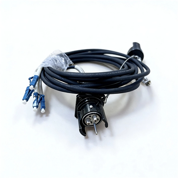
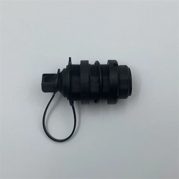
Answer: Ducts and bends choke bulky connectorized heads; long pulls would damage ends; and cumulative connector loss kills your budget. Splice pigtails locally; patch with jumpers on the front. Key. A fiber optic patch cord is a short-length cable (typically 1–10 meters) with pre-terminated connectors on both ends. Its primary function is to connect active network devices (e., switches, routers, transceivers) to passive components (e., patch panels, ODFs) or other devices. They act as the critical link for interconnecting devices like optical switches, servers, and distribution frames. Understanding the various technical. When designing a fiber network, one of the most common questions is: Should you use fiber optic pigtails or patch cords? While they may look similar, their functions are very different—and choosing the wrong one can impact performance and installation efficiency. Without them, even the best optical modules and switches cannot deliver performance. As data rates increase from 10G → 100G → 400G → 800G, patch cables must handle more bandwidth, more density, and stricter. A fiber optic patch cord (fiber jumper) is: Typical applications: A patch cord is the “bridge” that connects two fiber devices and lets them talk to each other. ZION Communication supplies both standard patch cords and custom assemblies to match your equipment, distance, and installation.
[PDF]

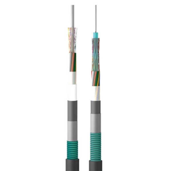
Selecting the right cable type ensures that the structure itself provides first-level protection. UV-Resistant Jackets (PE or LSZH): Prevent sunlight degradation. Water-Blocking Gel or Tape: Stops moisture migration inside the cable. Metal or Non-Metallic Armoring: Adds crush and. This guide covers how to safeguard outdoor fiber optics across underground, aerial, direct-burial, and exposed setups. Before applying protective measures, it's essential to understand the main risks fiber optic cables face outdoors. UV Exposure: Prolonged sunlight degrades standard plastic. Fiber optic cables are often used for long-distance communication due to their high bandwidth and low signal attenuation. Outdoor fiber optic cables are installed in harsh environments where they are exposed to various environmental factors such as temperature changes, humidity, moisture, dust, and. Optical cable lines lightning protection and strong current protection are achieved by avoiding, guiding or discharging them underground to prevent lightning and strong current from causing damage to the optical cable lines themselves, communication equipment and personnel. Since the lightning. The Fiber Optic Association, Inc. (FOA) was founded in 1995 to help develop the workforce to build the fiber optic networks to support a rapid expansion in communications and the Internet. Introduction: Why Fiber-Optic Cable Damage Matters Fiber-optic cables transmit data via pulses of light.
[PDF]
The answer is no; fiber internet doesn't need a traditional modem. A standard cable or DSL modem's job is to convert electrical signals into digital data that your devices can understand. But since fiber transmits data as light instead of electricity, there's no need for that type of. Instead, fiber relies on an Optical Network Terminal (ONT) to decode the signal from the fiber lines into something usable by your devices. In this way, an ONT serves the same basic function as a cable modem. However, ONTs tend to be much larger, so they are typically installed in closets, garages. The ONU connects directly to the fiber line entering the home. l It supports high speeds, often reaching 1 Gbps or more. l. While there are 137 residential internet providers in the state, most homes only have access to 1–2 options above 25 Mbps. California accounts for 12% of the US population, with 87% of California residents living in major urban centers like Los Angeles, Sacramento, and San Francisco. Instead, an Optical Network Terminal (ONT) is required to connect your home to the fiber network. In this guide, we'll explain how fiber internet works, why a modem isn't needed, and what equipment you. Your existing cable modem won't work with fiber service, and you'll need devices specifically engineered to convert optical signals into data your devices can use. Fiber internet relies on specialized equipment to deliver its high-speed, reliable performance.
[PDF]
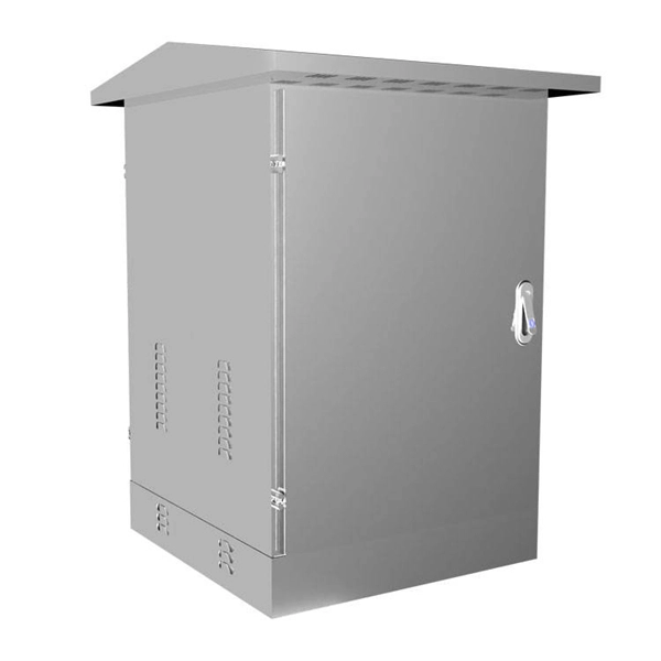
Secondary distribution boxes, also known as sub-distribution boxes, generally serve specific power supply areas. These boxes have inner and outer doors, powder-coated exteriors, and are designed for safety and aesthetic appeal, with rainproof tops for outdoor work. From the transformer's low-voltage side (0. 4kV), power is distributed to a main distribution panel (primary distribution box). From there, it is routed to individual building distribution boxes (secondary distribution boxes), which subsequently supply power to unit-level distribution boxes. Primary distribution systems consist of feeders that deliver power from distribution substations to distribution transformers. Many feeders leave substation in a concrete ducts and are routed to a nearby pole. Safe and beautiful, waterproof box top suitable for field work. It is specially designed for the special situation of the project construction site and meets the relevant construction power specifications and standards of the. Understanding the fundamental distinction between Primary and Secondary distribution in electrical systems is pivotal for designing efficient and reliable electrical distribution systems tailored to specific needs across various domains. Primary Distribution: Involves the transmission of high.
[PDF]

Optical fibers or fiber cables can be used for transmitting optical power from a source to some application. In their served areas will be power generating stations, alternative energy sources (solar, wind, geotherman, etc. ), substations for distribution and microgrids. These networks must be monitored and managed to ensure reliable power for the utility's customers. For monitoring and managing networks. Low voltage cables are mounted on poles in the "telecom space," well below power cables. Optical power ground wire (OPGW) is an electrical power ground with fiber optics in the center of the conductor. That conversion can be done with a photovoltaic cell. The Commission, on June 22, 1965, noting that the increasing demand for underground electric and communication facilities in California has brought about substantial increases in the construction of such facilities, and that it appeared it may be desirable, pursuant to Sections 761, 768 and 8056 of. One choice is optical power ground wire (OPGW). This conductive cable is run at the top of the tower or pole to be the ground conductor and protect the power cables from lightning. The fiber. While fiber optics is essential for internet service providers to deliver higher bandwidth and faster transmit speeds, there are also many crucial benefits of fiber optics in energy and power. Utility companies face various challenges as they work to deliver reliable energy to homes and industries.
[PDF]

An electrical distribution box is often called the control hub of a building's electrical system, and for good reason. It's where power from the main supply splits into different circuits that feed lights, appliances, and equipment throughout the building. Also known as a distribution board or breaker panel, it acts as the control hub, distributing power to different circuits and protecting them from overloads and faults. Here, we'll delve into what an electrical distribution box is, how it works, the components inside, types, and what to consider. A distribution box, also known as a distribution panel or board, is a cabinet that holds electrical parts used to supply power to multiple circuits within a system. It typically contains essential components such as circuit breakers, surge protectors. What Is a Distribution Box? Types, Uses & How to Choose A distribution box, also known as a power distribution box or electrical distribution box, is used to distribute electrical power safely to multiple circuits. Today, electrical systems are essential for homes and industries. This cabinet acts as the central hub for managing and directing power throughout a building. Inside, you will.
[PDF]

