By studying the expansion of Chinese telecommunications companies abroad, with a particular focus on Africa in our case study, the chapter aims to explore the relationship (i. partnership or/and competition) between African and Chinese telecommunications in. Chinese telecom infrastructure in Africa has expanded rapidly, embedding Beijing's influence into the continent's digital backbone. Upholding the principles of sincerity, real results, amity and good faith, China and African countries have achieved notable outcomes in infrastructure cooperation. Africa is China's. Chinese involvement in Africa's telecoms sector predates the DSR. The global advance of Chinese telecommunications firms, such as Huawei and Zhongxing Telecom Ltd (ZTE), was largely enabled by China's “go out policy,” which was launched in 1999 with the aim of promoting the internationalization of. According to the Tech Review Africa and Chinese Xinhua News, China Mobile officially activated 2Africa East Segment Submarine Cable on November 7, 2025, with an aim to power digital transformation across the African continent. The 2Africa submarine cable system, which spans 33 countries across. Infrastructure cooperation between China and Africa is thriving, and the outcome is changing the lives of millions. Industrial leaders and officials observed that the infrastructure projects undertaken by Chinese companies have yielded tangible benefits for Africans, helping the continent enhance.
[PDF]
Energy consumption growth of the fifth-generation (5G) mobile network infrastructure can be significant due to the increased traffic demand for a massive number of end-users with increasing traffic volum.
[PDF]
Power consumption of fiber optic cables can range from 0. 01-100 W/Gbps depending on the length of the cable (chart below). To ensure that fiber-optic connections have sufficient power for correct operation, calculate the link's power budget when planning fiber-optic cable layout and distances. The power budget is. Attenuation is the difference between the launch power of the signal from the transmitter and the power of the signal at the receiver. Each. The power consumption of coherent fiber-optical communication systems is beco-ming increasingly important, for both environmental and economical reasons. The data traffic on the Internet is increasing at a faster pace than that at which optical network equipment is becoming more energy efficient. With the growing global deployment of Fiber-to-the-Home (FTTH) networks driven by the demand for ensuring high-capacity broadband services, mobile network operators (MNOs) face challenges of excessive energy consumption (EC) of wired optical access networks (OANs). You use power budget calculations to verify whether an optical link—FTTH, ODN, backbone, or data center—can operate reliably under all. Reduced power consumption: 800G optical devices can achieve energy savings at the optical and system level, such as using more efficient modulation formats, optimizing circuit design, and reducing power density.
[PDF]

Voltage droop is the temporary reduction in the output voltage of a power source that occurs when the system suddenly draws a significant amount of electrical current. This drop is a fundamental consequence of electricity moving through materials that are not perfect conductors. The sudden increase. Voltage anomalies in telecom power systems disrupt network stability, often causing unexpected outages and costly downtime. Operators face significant challenges when faults go undetected, risking both equipment and service reliability. Power-related failures account for nearly one-third of telecom. Voltage stability in power systems can be impacted by various disturbances; including faults, load changes, equipment failures, and weather events. Instability can cause severe issues like loss of load, cascading outages, and the loss of synchronism in generators. Every conductor, regardless of material or size, possesses some amount of resistance that impedes current flow and converts electrical energy. Voltage dropping is a power quality condition where voltage at equipment terminals falls below expected operating levels during load conditions, causing instability, fluctuating performance, and observable changes in electrical system behavior. It is dynamic, load-driven, and often intermittent. Voltage drops and power losses in power lines are common and normal phenomena. They are associated with the flow of current through the different network components.
[PDF]
More than $69million (USD$30. 51m) will be channeled to Fiji in highly concessional capital via the multinational development partner-funded Climate Investment Fund (CIF) – to transform systems and enable the electricity grid to absorb and channel more clean power. The CIF governing board has. This International Merchandise Trade Statistics provides information on Fiji's exports, re-exports and imports of goods between Fiji and the rest of the world. The administrative data used to compile this release is supplied by the Fiji Revenue and Customs Service (FRCS). The REI Plan which represents a first-of-its-kind effort that will channel.
[PDF]
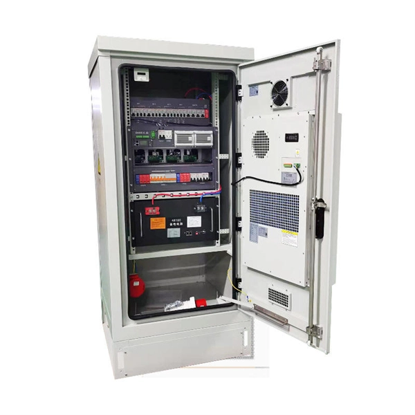
The key lies in their fully sealed design, acting as a “protective shield” for the cabinet, effectively preventing dust, salt spray, and high-temperature air from entering. So, how can this more reliable cooling solution become more economical to support large-scale 5G. ESTEL designs each Telecom Power System and outdoor telecom cabinet to adapt to these challenges. You get reliable performance through robust materials, smart energy management, and advanced engineering. ESTEL's dedication to quality, innovation, and international standards ensures your equipment. With 5G base stations, smart light poles, outdoor communication cabinets and other infrastructures spreading all over urban and rural areas, outdoor telecommunication equipments are facing severe tests such as extreme temperature difference, humidity and rain, and dust intrusion. Traditional. Available in different configurations, Delta OutD cabinets are designed to protect equipment from external threats in all climates from the tropics to the arctic. In addition to traditional cooling methods, Delta's new hybrid cooling options revolutionize the cost structure of thermal management. Featuring a robust steel structure with IP-rated protection, it ensures reliable operation against dust, rain, heat.
[PDF]
It can take primary power from a single source and then divides it among various secondary circuits. This process streamlines the wiring setup, making it easier to handle complex electrical configurations within an electrical panel. A distribution boxes is an essential device that manages the safe and efficient flow of electrical power throughout different areas of a building or facility. It is commonly used in homes, offices, and industrial settings to control and protect electrical circuits. Today, electrical systems are essential for homes and industries. Through its design and. A power distribution box is a key part of any electrical system. Without it, managing power would be messy, unsafe, and inefficient. At the heart of this network lies a power distribution box, the component responsible for dividing and controlling electricity as it moves from the main source to multiple end-use circuits.
[PDF]

Diagram showing positive tip polarity on the left and negative tip polarity on the right. To read diagram: The center positive drawing on the left indicates that the center (also known as the tip) of the output plug is positive (+) and the barrel (ring) of the output plug is negative. The center positive drawing on the left indicates that the center (tip) of the output plug is positive (+) and the barrel of the output plug is negative (-). Symbol for a center-positive power supply. It is always good practice to test. The term positive terminal describes which of the two connection terminals on direct current (DC) equipment supplies or is meant to receive a positive electrical charge. DC power supplies always feature a positive to negative electron flow and always have a negative and positive terminal. Polarity. It is defined by the positive and negative terminals of a power source, such as a battery. Understanding polarity is essential because connecting a device to a power source with the correct. The rating plate of an Extra Low Voltage Power Supply (ELVPSU) shows various symbols and abbreviations. These represent critical information about the supply's ratings, class, polarity, and other safety details. The polarity symbol indicates if the centre (or tip) of the output plug is positive (+).
[PDF]

What is the main cause of attenuation in fiber? Attenuation in fiber mostly happens from absorption and scattering. The fiber material takes in some light as it moves. Both of these things make the signal weaker as it goes through the. Optical Signal Attenuation is the single greatest factor limiting the distance and performance of your network. Understanding it is crucial for anyone involved in data centers, telecommunications, or enterprise networking. This guide will demystify signal loss, explore its causes, and show you how. Optical fibers are a key component in modern communication systems, carrying signals over long distances. However, even the most advanced optical fiber suffers from attenuation, which is the loss of signal power as it travels along the fiber. Understanding the causes of signal loss and implementing mitigation strategies is essential for maintaining network efficiency. From infrastructure planners to telecom engineers. Optical fiber technology enables rapid data transmission over vast distances by guiding light signals through thin strands of glass. Losses can be introduced by various means such as intrinsic material absorption, scattering, bending, connector loss and more.
[PDF]
Japan breaks the world record internet speed record: 1. 02 petabits per second via fiber optics, 4 million times faster than broadband. Breakthrough uses 19-core optical fiber, matching current cable thickness but with 19x the capacity. Technology maintains speed over 1,120 miles, solving long-distance signal loss with. Most fiber providers offer plans with speeds of at least Gbps (1,000 Mbps), but this is by no means the limit to fiber technology. Some providers already offer multigigabit speeds, such as AT&T's 5 Gbps (5,000 Mbps) fiber plan. Google owns an undersea fiber-optic cable connecting North America and. There is a new world record for fiber speed: 1. Here is how these fiber speed records compare: Faster fiber optic networks help you get real-time updates for. At the heart of this breakthrough – driven by Japan's National Institute of Information and Communications Technology (NICT) and Sumitomo Electric Industries – is a 19-core optical fiber with a standard 0. 125 mm cladding diameter, designed to fit seamlessly into existing infrastructure and. In a groundbreaking feat that promises to redefine global communication capabilities, Japanese researchers have achieved an unprecedented data transmission speed of 1. The achievement yielded a capacity–distance product of 1. That rate is about four million times higher.
[PDF]

This standard covers the construction, mechanical, electrical, and optical performance, installation guidelines, acceptance criteria, test requirements, environmental considerations, and accessories for a nonmetallic, all-dielectric self-supporting (ADSS) fiber optic cable. An All-Dielectric Self-Supporting (ADSS) cable operates without metallic messengers, relying entirely on its aramid yarn strength members. For a typical 12-fiber ADSS cable with a 8. AFL-ADSS® (All-Dielectric Self-Supporting) cable is ideal for installation in distribution as well as transmission environments. This guide provides general recommendations for the selection of methods, equipment, and tools for the stringing of ADSS (All Dielectric Self-upporting) fiber optic cables including short and Long Span ADSS cables. The installation methods for ADSS cables are essentially the same as those used for. This Installation Manual is a recommendatory installation document provided by HANGZHOU ZION COMMUNICATION CO. The installation manual is established based on the newest issued international standards such as lEEE Std 1222: 2004, "lEEE standard for all-dielectric. Round aramid reinforced ADSS cable for intermediate and long spans, 4 – 96 fibres. VDE: A- DF 2Y (ZN) 2Y This specification covers a family of optical cables with 4 - 96 fibres for intermediate and long spans.
[PDF]

Electricity enters the box via the main breaker from the utility or generator. Power is passed to bus bars and adjusted to usable voltages (e. Breakers direct power to each circuit and trip during overloads. Neutral returns current; ground directs stray. A power distribution box (DB box) works by serving as a central electrical panel where electrical power is received and distributed from one input source to multiple output sources. This distribution box ensures the safe distribution of power throughout a building or area. Through its design and. A switchboard is a component of an electrical distribution system which divides an electrical power feed into branch circuits while providing a protective circuit breaker or fuse for each circuit in a common enclosure. Switchboards typically have a maximum voltage rating of 600 Vac/Vdc and a. A distribution box is a key part of electrical systems in buildings. Inside, you'll find parts like circuit breakers and fuses that protect the system from problems like overloads and short circuits. It ensures that electricity flows. Breakers are switches that turn off automatically when there's too much electricity or a short circuit. This helps prevent fires or damage. Without it, your devices and appliances could be in. Electrical switchboards are fundamental in controlling and distributing electricity in homes, offices, and industrial settings.
[PDF]
Electric power distribution systems are designed to serve their customers with reliable and high-quality power. The most common distribution system consists of simple radial circuits (feeders) that can be ove.
[PDF]

Traditional pluggable optical modules are approaching their physical limits in three core dimensions: power consumption control, signal integrity and port bandwidth density. Low Latency: LPO technology eliminates the need for a DSP, reducing a processing step and thus lowering data transmission latency. This advantage is particularly important in high-performance computing (HPC) scenarios, where minimizing latency is a key factor in achieving optimal performance. By. Among the emerging technologies, LPO (Linear Pluggable Optics), NPO (Near-Packaged Optics), and CPO (Co-Packaged Optics) represent three important stages in the evolution of next-generation data center optical networking. Understanding how these architectures differ is essential for designing. Optical communications are emerging as the next AI computing infrastructure frontier, driven by data interconnection bottlenecks. Lumentum's order book is full through 2028, reflecting surging demand for 800G and 1. 6T optical modules, amplified by Nvidia's strategic investment., May 4, 2026 – GlobalFoundries (Nasdaq: GFS) (GF) today announced the introduction of its SCALE™ optical module solution for co-packaged optics (CPO). GF's SCALE. In Feb. 2023, the State Council issued the "Overall Layout Plan for Digital China Construction. ” It proposes six key tasks,including enhancing the efficient.
[PDF]
In this guide, we'll break down everything you need to know to install a distribution box correctly and confidently. Choose the right box based on environment (indoor/outdoor), load capacity, and durability. Check for proper IP/NEMA ratings and material quality. This section includes guidelines for the construction, installation, and inspection of electrical systems. Review Part 4, “Highway Traffic Signals,” of the California Manual on Uniform Traffic Control Devices; California Code of Regulations, Title 8, “Electrical Safety Orders,” (8 CCR 2299 et. The QUAZITE® H20 enclosures include a rugged polymer concrete box with a galvanized steel frame and cover surrounded by a minimum of 3 inches of cast-in-place concrete. For scenarios that could benefit from this type of enclosure, read our blog. When is a roadway like a bridge? Any underground. Learn how to wire a distribution box step by step! This video shows real on-site footage of electrical installation, demonstrating safe and standardized wiring methods used by professionals. Covers wiring, placement, standards, and expert tips for a compliant setup. It takes the incoming power and safely distributes it to different circuits throughout your building. the shoulder surface. Restore the disturbed area around the pull box and m cover of 12 inches. Otherwise, provide a minim.
[PDF]