The typical specification range of return loss of a fiber connector is -15 dB to -60 dB. Return loss is also known as reflection loss. It indicates the amount of signal reflected back to the transmitting end. Return loss refers to the power loss caused by the reflection of part of the signal back to the signal source during transmission due to the discontinuity of the transmission. Insertion loss, also known as attenuation, is the loss of optical power that occurs when light passes through a fiber optic connector. It is caused by factors such as misalignment, air gaps, and imperfections in the connector components. The lower the insertion loss, the better the performance of. Reflectance (which has also been called "back reflection" or optical return loss) of a connection is the amount of light that is reflected back up the fiber toward the source by light reflections off the interface of the polished end surface of the mated connectors and air. It is also called. Insertion Loss (IL) is the amount of optical power lost as the signal travels from one point to another in a fiber optic link, usually across connectors or splices. Formula for. In optical fiber communication, insertion loss and return loss are two important parameters to evaluate the quality of interfaces between some optical fiber components, such as optical fiber connector, fiber patch cable, pigtail fiber, etc. While it's natural to have.
[PDF]

Optical return loss is the amount of light that is reflected back to the source, this reflected light is measured at each connector and splice at each point over the entire fiber link. This is always measured in dB (decibels) and will be displayed as a negative number. The closer the number is to. The polish of a singlemode fiber endface plays a significant role in reflectance. Understand what you need before you specify. The Institute of Electrical and Building the ORL story Electronics Engineers (IEEE) recently Within a fiber-optic channel or path-released new specifications within way. Optical Return Loss (ORL) in fiber optics refers to the amount of light that is reflected back toward the source in a fiber link. ORL is usually expressed in decibels (dB) as a positive value, with. Return loss (RL) is also called reflection loss. When high-speed signals enter or exit a part of an optical fiber, such as an optical fiber connector, discontinuity and impedance mismatch may cause reflection, which is the return loss of an optical fiber. Poor ORL is commonly caused by dirty connectors, poor splices, mismatched connector types, or damaged fibers. ORL is measured using ORL meters. Home Coherent Optics Optical Return Loss (ORL) Explained Comprehensive Guide to Understanding and Managing Back-Reflections in Fiber Optic Systems What is Optical Return Loss (ORL)? Optical Return Loss (ORL) is a critical parameter in fiber optic systems that quantifies the amount of light.
[PDF]

The max insertion loss of a fiber patch cable is 0. 75 dB (the maximum acceptable value) in the TIA standard. Insertion loss (IL) and return loss (RL) are key performance indicators of fiber optic patch cords. This article explains their concepts, standards, testing methods, and FiberMania's quality assurance workflow to ensure optimal network performance. Fiber optic patch cords are crucial components in. A: Fiber optic loss refers to the reduction in signal strength as it travels through the fiber optic cable. This can be due to various factors, including attenuation, connectors, and splices. Q: How is fiber optic loss measured? A: Fiber optic loss is typically measured using an Optical Loss Test. The estimate, called a "loss budget" is calculated using typical component losses for each part of the cable plant - the fiber, splices and/or connectors. If the measured loss exceed the calculated loss by a significant amount (remembering the inherent uncertainty in all measurements), the system. Insertion loss is usually shortened to IL, and the unit of measurement for insertion loss is dBm. ) in transmission systems. It is the power attenuation of the signal after. At TARLUZ, we specialize in manufacturing high-performance fiber optic patch cords that comply with global industry standards, ensuring optimal signal integrity and long-term stability.
[PDF]

GOOD WILL INSTRUMENT (SUZHOU) CO. Browse online or download User Manual for Equipment Gw-instek GOS-652G. GW Instek GOS-652G User Manual 50MHz Cursor Readout With Delayed Sweep.. GOS-658G 20MHz Cursor Readout... GOS-652G 35MHz. Caution statements identify conditions or practices that could result in damage to this product or other property. THIS APPLIANCE MUST BE the letter E or by the earth symbol or coloured Green or Green & Yellow. EARTHED The wire which is coloured Blue must be connected to the terminal which is. y have a fraction of the total loss compared to fiber-based equivalents. FBG also provides a latency in the o der of nanoseconds as compared to microseconds in fiber-based solutions. The FBG based DCMs are designed to perfectly mimi the dispersion and dispersion slope characteristic of G. 652 fiber. g sensitivity and low water-peak level. Together they allow unlimited use of the whole telecom wavelength win ow for a great variety of applications.. GOS-653G Basic... GOS-622G. The GOS-653G/652G Series is an example of classic analog oscilloscope design. The GOS-653G /652G cover a broad range of industry applications, such as product design, assembly lines, repair & servicing, and educational purposes for EE laboratories and class experiments. Coupled with various trigger.
[PDF]
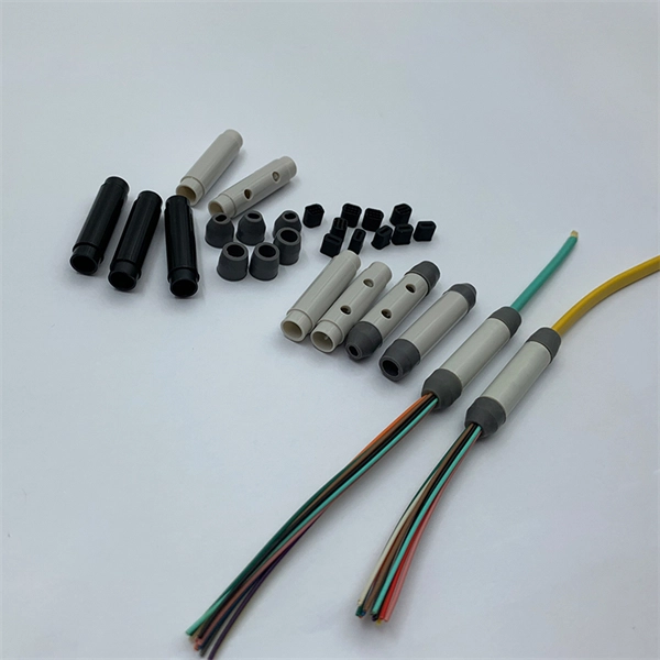
Featuring SC UPC connectors on both ends, it delivers low insertion loss and stable signal transmission. Its simplex structure and durable cable jacket make it suitable for a wide range of fiber optic installations. The SC/APC pre-polished fast connector comes pre-adjusted from the factory, with field-installable connectors that completely eliminate the need for hand polishing in the field. Proven mechanical splicing technology ensures precise fiber alignment, a factory-prepared fiber end, and a combination of. Technovate International Pvt. Ltd was established in 2017 with an objective to provide end-to-end fiber optic products and solutions to Internet Service Providers (ISPs) and Cable TV Operators in Nepal; and also supplying telecommunication equipment. We mostly import goods directly from our partner. Nepal - Shop for Best Online at Daraz. np Wide Variety of optic fiber sc connector. Great Prices, Even Better Service. 0mm Simplex is a high-quality fiber optic patch cable designed for reliable connectivity in telecommunications and networking applications.
[PDF]
Fiber optic connectors in SFP modules are the physical interfaces that connect the transceiver to fiber patch cables, enabling optical signal transmission between network devices. Fiber optic connectors are silently the hero that make fiber networks to have secure, low loss, and easy maintaining connections. In their absence, it would be the only possible approach, splicing that is, which, indeed, is costly and time consuming besides irreversible. These connectors play a. A fiber optic connector is a mechanical device used to align and join optical fibers, enabling light to pass through with minimal loss. This allows for quickly connecting and disconnecting of fiber optic cables without splicing.
[PDF]
Nigeria Fiber Optic Connectors Directory provides list of Made in Nigeria Fiber Optic Connectors Products supplied by reliable Nigeria Fiber Optic Connectors Manufacturers, Traders and Companies. Don't know your target market? Wanted to market your Fiber Optic Connectors products. 3m SC-ST Single-Core Multi Mode Fiber Optic Jumper1. Product name: SC-ST Fiber Optic Jumper 2. Color: Orange feature 1. Low insertion loss 2. Not easy to damage 4. Discover the essential Fiber Optic Cable Connector Kit, designed for seamless connectivity and optimal performance. Perfect for both professionals and DIY enthusiasts, this kit includes everything you need for efficient fiber optic installations and repairs. Enhance your network's reliability and. This is a comprehensive FTTH (Fiber To The Home) fiber optic termination tool kit used for. Original 4k 8k fiber optic cable, highly compatible for all HD resolution Fiber optic strands. The VIS4000D is a mini-pro, 11-in-1, or 12-in-1 handheld optical time-domain reflectometer (OTDR). With their commitment to quality and customer satisfaction, they are revolutionizing the telecommunications industry one cable at a time. Join us as we explore how.
[PDF]
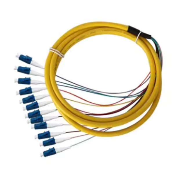
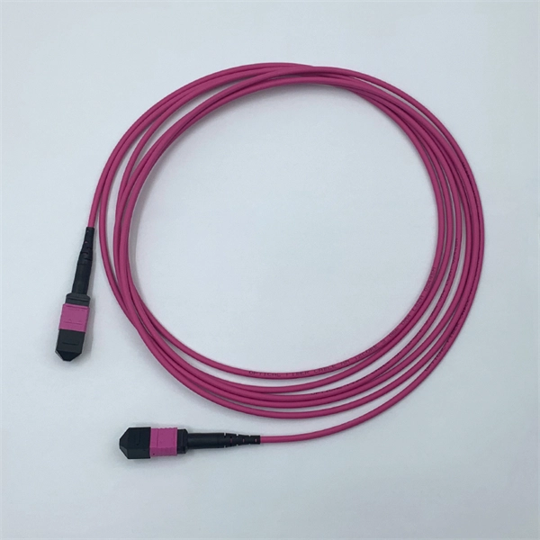
Answer: Ducts and bends choke bulky connectorized heads; long pulls would damage ends; and cumulative connector loss kills your budget. Splice pigtails locally; patch with jumpers on the front. Key. A fiber optic patch cord is a short-length cable (typically 1–10 meters) with pre-terminated connectors on both ends. Its primary function is to connect active network devices (e., switches, routers, transceivers) to passive components (e., patch panels, ODFs) or other devices. They act as the critical link for interconnecting devices like optical switches, servers, and distribution frames. Understanding the various technical. When designing a fiber network, one of the most common questions is: Should you use fiber optic pigtails or patch cords? While they may look similar, their functions are very different—and choosing the wrong one can impact performance and installation efficiency. Without them, even the best optical modules and switches cannot deliver performance. As data rates increase from 10G → 100G → 400G → 800G, patch cables must handle more bandwidth, more density, and stricter. A fiber optic patch cord (fiber jumper) is: Typical applications: A patch cord is the “bridge” that connects two fiber devices and lets them talk to each other. ZION Communication supplies both standard patch cords and custom assemblies to match your equipment, distance, and installation.
[PDF]
There are connectors designed for single mode and multimode fiber optic cables, which differ in core size, bandwidth, and optimal use cases as explained in this comprehensive guide to fiber optic cable.
[PDF]
Get the wrong connector type, the wrong polish, or skip proper fusion splicing technique—and you're looking at elevated signal loss, increased back reflection, and a field termination that fails certification. Thoracostomy tubes are indicated for management of air or fluid in the pleural cavity. Pigtail catheters have emerged as an effective and less morbid alternative to traditional large bore chest tubes for evacuation of pleural air or fluid. However, they do not come without complications which. Traditionally large-bore tube thoracostomy has been the standard of care for treating many acute intrathoracic pathologies. However, the advent of less invasive small-bore chest tubes, also known as pigtail catheters, has gradually led to a paradigm shift. They are used to treat a variety of conditions including pneumothorax, pleural effusion, and postoperative evacuation of air and fluid. There are a number of types and sizes of chest tubes available ranging. Return loss is the ratio of signal power injected from a source compared to the amount that is returned or reflected back toward the source. It is a critical performance parameter in both copper twisted pair and fiber optic cabling systems, because it can interfere with the transmitted signal and. Executive Summary: A fiber optic pigtail is one of the most commonly specified yet least understood components in structured cabling.
[PDF]

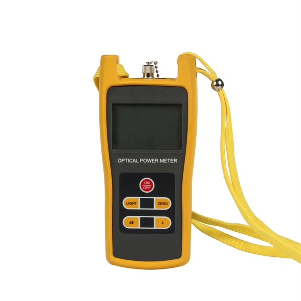
Select the correct wavelength and set your reference. You measure optical power in dBm or insertion loss in dB. Consistent procedures ensure accuracy. Measure total signal loss from fiber, connectors, or splices. Optical fiber attenuation is the attenuation per unit length of optical fiber, and the unit is dB/km. When connecting two optical fibers, there will be loss inside any connector or joint. Consistent measurement techniques. While optical power meters are the primary power measurement instrument, optical loss test sets (OLTSs) and optical time domain reflectometers (OTDRs) also measure power in testing loss. TIA standard test FOTP-95 covers the measurement of optical power. Optical power is based on the heating power. Light Source: The CMA5 Series Light Sources provide an economical and stable laser source for use in point-to-point attenuation measurement. They feature a rugged design, built to withstand the difficult testing environment of fiber optic cable installation and maintenance. The CMA5 Light Sources. When talking about optical measurements, wavelength basically means how far a wave pattern repeats itself, usually measured in nanometers (nm). Commonly, a power meter on its own is used to measure absolute.
[PDF]

5 dB depending on splitter type. Common planning value: 0. Optional: patch panels, attenuators, or extra components. Helps cover dirt, aging, and measurement tolerances. Adds Rx power and margin calculation. Use 2×N when two inputs feed the same distribution stage. Wavelength is recorded in outputs for documentation. Optional: patch. FTTH / PON Splitter Loss Calculator - Zion Communication is a professional manufacturer of cables and accessories for signal and low voltage transmission. Estimate whether an FTTH or PON optical link is feasible by calculating PLC splitter loss, fiber attenuation, connector loss, splice loss and. In fiber optic networks, particularly in FTTx (Fiber to the x) and PON (Passive Optical Networks) deployments, splitters play a central role in distributing the optical signal from a single source to multiple destinations. These are known as passive optical splitters, and they perform the function. The formula for the theoretical loss for each output port of a splitter with N output ports is: Theoretical Split Loss (in dB) = 10 * log10 (N) Where: N is the number of output ports the splitter has (e., 2 for a 1x2 splitter, 4 for a 1x4, 8 for a 1x8, 32 for a 1x32, etc. Passive split links usually lose the most dB at the splitter, so we keep the optical budget and the installed route separate. These are especially important for FTTH (Fiber to the Home), data centers, and Passive Optical Networks (PON), where.
[PDF]
In 5G fronthaul and backhaul networks, Small Form-factor Pluggable (SFP) modules are often the bridge between optical network elements and fiber paths. Clean, well-maintained fiber connectors are critical for maintaining low insertion loss and minimizing reflected power. In practice, dirty or. This article explores the wide range of fiber optic connector types, from legacy SC and ST to modern MPO/MTP and VSFF designs. Learn how each connector works, where it's used, and how to choose the right option for today's high-density, high-speed networks. Fiber optic connectors may look small. Fiber optic connectors are mechanical devices that join optical fibers with minimal signal loss, enabling high-speed data transmission. Key performance metrics include: Insertion Loss: ≤0. The performance of these networks heavily depends on the quality of optical connectors and splicing techniques used during installation and maintenance. They link fiber optic cables, allowing data to move quickly with minimal loss.
[PDF]
In the rapidly evolving landscape of modern networks, fiber optic connectors play a pivotal role in ensuring seamless data transmission and connectivity. These essential components bridge fibers, enabling the efficient transfer of information across various applications and. Among these components, fiber connector types are essential to network performance, reliability, and scalability. This guide will walk you through the most common fiber connector types, explaining their characteristics, advantages, and typical use cases. The connector body, which is the protective housing that holds and protects the ferrule, plays a key role in ensuring a robust and durable connection. Fiber optic connectors can. Whether it's for internet networks, telecommunications, or data centers, fiber optic cables rely heavily on connectors to establish secure and efficient connections. They link fiber optic cables, allowing data to move quickly with minimal loss. In this guide, you'll explore various types of fiber optic cable connectors, each with unique features and. Learn about the top 4 fiber optic connectors (LC, SC, ST, MTP/MPO) and find the best options for your network, optimizing performance, reliability, and data transfer in a technological age.
[PDF]
Large-scale, densely distributed fiber Bragg grating (FBG) arrays have a wide range of applications in industrial safety surveillance. Due to the limitation of inscription pulse-width, most grating interrogator.
[PDF]