The development of the relay protection based on open architecture is a relevant direction of electrical and electronic engineering. The paper presents the problem of the modern microprocessor-based relay prote.
[PDF]
Pilot-wire relaying is an adaptation of the principle of differential relaying to line protection and functions to provide high-speed clearing of the line for faults anywhere on the line. Pilots include wire pilot (us.
[PDF]

To provide effective and reliable protection to the power system, a protective relay must have the following essential functional characteristics: Selective, Fast, Stable, Reliability, Sensitivity, Simple Construction and Installation Mechanism, and Cost-effective. Characteristics of Protective Relay elements using different operating principles. These principles and design criteria determine how well the basic function is performed and how in practice it deviates from the ideal. These are some essentially. What is a Protective Relay? – Functions, Types & Applications Reliability and safety are paramount in the vast and intricate power systems world. Enter the protective relay, a crucial device designed to detect and respond to abnormal conditions, faults, and disturbances in electrical networks. Types of Protective Relays: Protective relays are categorized by their mechanism (electromagnetic, static, mechanical) and function. A protection relay is a crucial component of electrical systems that safeguard infrastructure, employees, and equipment from electric problems and malfunctions. It functions as a watchdog by constantly surveying multiple system components including voltage, current, frequency, and phase angle. Based on Operating Principle Electromechanical Relays: Work using moving parts and electromagnetic forces (traditional.
[PDF]

Their core functions can be summarized as: enabling efficient cable branching, safe isolation, flexible control, and reliable protection of cable lines, thereby improving the reliability, flexibility, and maintainability of the power distribution network. A distribution box, often simply called a DB, is a crucial component in any electrical installation. Think of it as the heart of your building's electrical system. Just as a heart receives blood and pumps it to various parts of the body, the distribution box receives the main electrical supply and. Safety protection function in low voltage distribution boxes prevents electrical hazards and ensures reliable, secure power distribution for your operations. You rely on the safety protection function of a low voltage distribution box every day. These safety protection function features guard you. A distribution boxes is an essential device that safely and efficiently distributes electrical power to different areas within a building or facility. It is commonly used in homes, businesses, and industrial settings to control and protect electrical circuits. Today, electrical systems are essential for homes and industries. Understanding its significance.
[PDF]

Numerical relay are embedded with specialized digital signal processor (DSP) as the computational hardware. By using DSP as the relay's processor, the relay is capable of meeting the fundamental protective requirements such as reliability, sensitivity, selectivity and speed . Thus, various protective devices are used to protect the power system, of which digital signal processor (DSP) numerical relays are capable of significantly improve protection operations. Therefore. Manuals and User Guides for Samwha DSP DSP-VIP-PM Motor Protection. We have 1 Samwha DSP DSP-VIP-PM Motor Protection manual available for free PDF download: Manual Samwha dsp DSP-VIP-PM Motor Protection Pdf User Manuals. View online or download Samwha dsp DSP-VIP-PM Motor Protection Manual. Many of the new protection relays are microprocessor based and are generally referred to as numerical relays. This means that signals from transducers are sampled at fixed time intervals, digitally encoded, and processed by equipment which resembles a computer to derive relaying information, e.
[PDF]
In electric power systems and industrial automation, ANSI Device Numbers can be used to identify equipment and devices in a system such as relays, circuit breakers, or instruments. The device numbers are enumerated in ANSI/IEEE Standard C37.2 Standard for Electrical Power System Device Function Numbers, Acronyms, and Contact Designations. Many of these devices protect electrical. List of device numbers and acronyms• 1 - Master Element• 2 - Time-delay Starting or Closing Relay• 3 - Checking or Interlocking Relay, complete Sequence• 4 - Master Protective. A suffix letter or number may be used with the device number; for example, suffix N is used if the device is connected to a Neutral wire (example: 59N in a relay is used for protection against Neutral Displacement); and suffixe.
[PDF]

Work From Home Relay Protection Engineers often face challenges related to coordinating with on-site teams, accessing physical equipment remotely, and ensuring clear communication during installations and troubleshooting. In this comprehensive article, we delve into the best practices, challenges, and innovative solutions in relay testing and commissioning, placing a strong emphasis on. Relay protection is the discipline of designing schemes that detect faults, coordinate relays, and isolate equipment without outages. It emphasizes selectivity, coordination, fault response, and system behavior rather than individual relay devices. Relay protection is often misunderstood as a. What are the top challenges that a Protective Relay Technician might face in the first 90 days? What does a day in the life of a Protective Relay Technician look like? What are some tips for helping a Protective Relay Technician fit into the company culture? What are some career development tips. fer more functions than ever. Substation Protection and Control (P&C) systems based on the IEC 61850 standard and energy sources from inverter-based renewable of engineers and technicians. In complex power networks, coordination between protective devices becomes essential to ensure selective operation and minimize disruptions. However, achieving coordination.
[PDF]

The main group of impedance relays is distance protection devices. loss of synchronism protection, loss of excitation protection, or impedance automatics like fault locator. Impedance Relay Definition: An impedance relay, also known as a distance relay, is defined as a device that triggers based on the electrical impedance measured from a fault's location to the relay. Working Principle: The operation of an impedance relay hinges on the balance of voltage-induced. When a system has too many radial lines protection using time delay overcurrent relay becomes impractical. This problem can be solved to an extent by using distance relays. Distance relays uses voltage and current to calculate the. Distance relay protection has been defined as a part of relay protection in power systems that detects and isolates faults based on the distance between the relay and fault points. Unlike overcurrent relays, which only respond to the magnitude of current, a distance relay measures the impedance of. Such relays are called Distance Relays or Impedance Relays. In an impedance relay, the torque produced by a current element is opposed by the torque produced by a voltage element. The relay will operate when the ratio V/I is less than a predetermined value. The voltage transformer measures the voltage across the protected equipment, while the current transformer measures the current flowing through it.
[PDF]

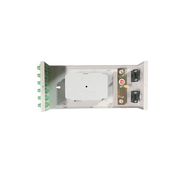
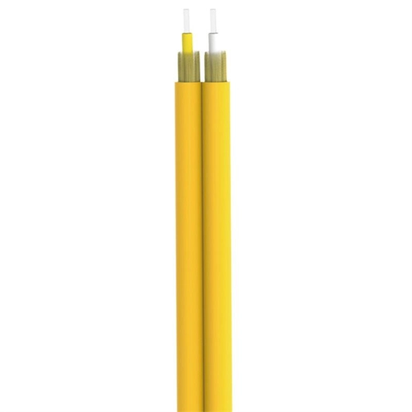
Product Features: Square protective box, suitable for skin cable and leather cable tight protection 6cm in length of skin heat shrink tube welding protection. A close connection between the leather cable and pigtail. Looking for specific info?. *In the era of high bandwidth, reliable fiber optic power equipment is particularly important. This handheld photometer can help check cable performance, calculate relative power loss, locate faults, and troubleshoot. *Measure the length of network cables, coaxial cables, and telephone cables. Able. Usually ships within 3 to 4 weeks Click here for details of availability. Able to test open, short, cross-connect, See more product details TABKER 4000667180167 3 x 2 x 1. Check each product page for other buying options. Price and other details may vary based on product size and color. Need help?. power across any given fiber. This document will serve as an overview of the major features and functions of the device and will ofer tips for trouble shooting com on issues in optical networks. If you are looking for a low cost device capable of saving and reporting take a look at the RP460 or. ments to the instrument's performance and functionality. The figures given in this manual ion of this manual to ensure the accuracy of its contents. However, should you have any questions or fi gistered users with a variety of information and services. Please allow us to serve you best by.
[PDF]
This paper analyzes the basic principle and function of relay protection, summarizes the common fault types, and analyzes the fault analysis methods and treatment measures combined with actual cases. A method of fault tracking for relay protection devices is presented in this paper. Fault tracking means that after the failure of relay protection devices, the anomalies and warning informa-tion are obtained through data-mining technology, and then, the fault tracking algorithm is used. Relay fault diagnosis refers to the process of identifying and analyzing faults or abnormalities in protective relays. However, in actual operation, the relay protection device may cause failure due to hardware failure, software problems or external. For a long time, the fault diagnosis technology of relay protection consists of isolated cases and does not have a systematic method.
[PDF]
Distance relays, also known as impedance relay, differ in principle from other forms of protection in that their performance is not governed by the magnitude of the current or voltage in the protected circuit but rather on the ratio of these two quantities.OverviewIn, a protective relay is a device designed to trip a when a is detected. The first protective relays were electromagnetic devices, relying on coils operating on moving par. Electromechanical protective relays operate by either, or. Unlike switching type electromechanical with fixed and usually ill-defined operating voltage thresholds. Electromechanical relays can be classified into several different types as follows: "Armature"-type relays have a pivoted lever supported on a hinge or knife-edge pivot, which carries a moving contact. These relays may.
[PDF]

Cable trays play a key part in keeping fire protection systems working. Here is what they do: They Make Safe Paths for Fire System Wires Cable trays are made from materials that resist fire. They can help stop fire from spreading. Recognize electrical cable tray misuse that can lead to electric shock and arc-flash/blast events and fires caused by overheating. The use and installation of cable trays is covered by legally enforceable OSHA regulations in 29 CFR 1910. 305(a)(3), or comparable standards promulgated by States. Scope: Firestopping for busway, cable trays, cables, and trunking passing through walls in enclosed electrical installations. Where cables pass through shafts, walls, slabs, or enter electrical panels or cabinets, openings shall be tightly sealed with firestopping materials in accordance with. Cable trays can be part of a planned cable management system to support, route, protect, and provide a pathway for cable systems. Power, low voltage control, data, or telecommunications wiring distribution systems can be used with cable trays. 1 This section applies to cable trays utilized to support and route low voltage cables (telecom, security, A/V). No fire alarm cables will be permitted to be installed in cable trays. If a fire starts, the tray protects the wires inside from flames and.
[PDF]

A slight breaker box humming noise from your electrical panel is highly normal and should not be of concern to you. To explain, what you're mainly hearing is the flow of electrical current within the circuitry of your home. There are plenty of reasons why you hear that electrical box humming noise. For easier reading, I have listed the reasons why your circuit breaker buzzes when turned on. The causes are organized according to their severity. Faint Circuit Breaker Buzzing Now, faint, distinct buzzing emanating. What Causes Buzzing Sounds in Your Electrical Panels? Hearing buzzing sounds in your electrical panel? Learn what causes it, when it is dangerous, & how The Electricians can help keep your home safe. Some common reasons for electrical humming or buzzing noises include: If electrical wires are not properly secured or damaged, they can vibrate and emit a humming noise. This could be due to natural wear and tear, poor installation, or animals chewing on exposed wiring. While a faint, steady hum from a transformer or large appliance is sometimes a normal byproduct of electrical flow, loud or irregular noises often signal an. Your electrical panel making noise can be disconcerting because these sounds typically indicate underlying issues you must address promptly. Even while you shouldn't be overly concerned when you hear this sound, there are some cases in which it could indicate that there is a major issue with the electrical system in.
[PDF]
These are single- or multi-conductor control cables designed for use in trays or substations. They feature insulation made from XLPE, EPR, PE, or PE/PVC, and are protected by jackets made of CPE, PVC, or LSZH. Our cables are suitable for various installations, including cable trays, direct burial. Substation Control Cable is a general purpose control cable, which is primarily used in industrial and utility applications, for distribution or control circuits and for the interconnection of operation of protective devises. Substation Control Cable can be installed in open air, in ducts or. Lightera products are used in electrical substation automation applications. Competitively priced and designed for minimal environmental impact, this cabling solution allows for reliable. Abstract:The design, installation, and protection of wire and cable systems in substations are covered in this guide, with the objective of minimizing cable failures and their consequences. These cables are crush resistant, have a high degree of varying temperature ranges (from -50c to +75C), are easy to terminate, and can withstand any environment. Power Cables High Voltage (HV) Cables: Used to transmit.
[PDF]
Wiring a CCTV Camera to Power Supply Box with Premade Siamese CableThis video shows installers how to connect a CCTV camera to a 12V DC power supply box using premade Siamese security camera cables. The process is e. Wiring a CCTV Camera to Power Supply Box with Premade Siamese CableThis video shows installers how to connect a CCTV camera to a 12V DC power supply box using premade Siamese security camera cables. The process is exactly the same for 24VAC power supply boxes, except that the cable polarity does not matter with alternating current (+ and - does not matter with 24VAC wiring). Our latest model power supply boxes use PTC auto reset fuses instead of traditional one time use fuses. The above image shows a power supply box on the left that uses traditional fuses. The one on the right is our latest generation model, which uses PTC. PTC is much more convenient because when there is a short circuit, the PTC turns the circuit of. Below are some examples of how multi-channel power supply boxes can be installed with analog CCTV cameras, HD security cameras, and audio surveillance microphones. We have the following complete how-to guides available. Please use the below links to access complete guides. 1. Security Camera Installation Using RG59 Siamese Coax Cable Spools 2. Secu. Here are the most common ways that power supply boxes are used in video and audio surveillance installations. Please access the detailed guides using the above links.
[PDF]


