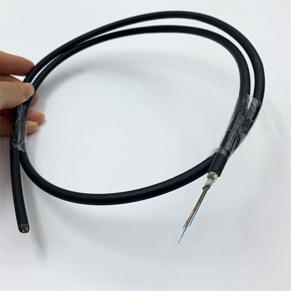
This standard covers the construction, mechanical, electrical, and optical performance, installation guidelines, acceptance criteria, test requirements, environmental considerations, and accessories for a nonmetallic, all-dielectric self-supporting (ADSS) fiber optic cable. An All-Dielectric Self-Supporting (ADSS) cable operates without metallic messengers, relying entirely on its aramid yarn strength members. For a typical 12-fiber ADSS cable with a 8. AFL-ADSS® (All-Dielectric Self-Supporting) cable is ideal for installation in distribution as well as transmission environments. This guide provides general recommendations for the selection of methods, equipment, and tools for the stringing of ADSS (All Dielectric Self-upporting) fiber optic cables including short and Long Span ADSS cables. The installation methods for ADSS cables are essentially the same as those used for. This Installation Manual is a recommendatory installation document provided by HANGZHOU ZION COMMUNICATION CO. The installation manual is established based on the newest issued international standards such as lEEE Std 1222: 2004, "lEEE standard for all-dielectric. Round aramid reinforced ADSS cable for intermediate and long spans, 4 – 96 fibres. VDE: A- DF 2Y (ZN) 2Y This specification covers a family of optical cables with 4 - 96 fibres for intermediate and long spans.
[PDF]

Traditional pluggable optical modules are approaching their physical limits in three core dimensions: power consumption control, signal integrity and port bandwidth density. Low Latency: LPO technology eliminates the need for a DSP, reducing a processing step and thus lowering data transmission latency. This advantage is particularly important in high-performance computing (HPC) scenarios, where minimizing latency is a key factor in achieving optimal performance. By. Among the emerging technologies, LPO (Linear Pluggable Optics), NPO (Near-Packaged Optics), and CPO (Co-Packaged Optics) represent three important stages in the evolution of next-generation data center optical networking. Understanding how these architectures differ is essential for designing. Optical communications are emerging as the next AI computing infrastructure frontier, driven by data interconnection bottlenecks. Lumentum's order book is full through 2028, reflecting surging demand for 800G and 1. 6T optical modules, amplified by Nvidia's strategic investment., May 4, 2026 – GlobalFoundries (Nasdaq: GFS) (GF) today announced the introduction of its SCALE™ optical module solution for co-packaged optics (CPO). GF's SCALE. In Feb. 2023, the State Council issued the "Overall Layout Plan for Digital China Construction. ” It proposes six key tasks,including enhancing the efficient.
[PDF]

A single strand of glass fiber, called single-mode fiber, is used to transmit single-mode or light beams. It can transmit higher bandwidth than multimode fiber but requires a light source with a limited spectral range. There are mainly two types of optical fibers, single-mode optical fiber, and multimode optical fiber, which differ in the way light propagates. The latter is used for short-distance transmission, while the former is typically used for long-distance signal transmission. Please refer to the article. Single fiber modules (BiDi) use one fiber for both transmitting and receiving data. This saves space and money. Dual fiber modules use two fibers. They are easier to set up and give steady communication. Single-mode optical modules are best for long distances and fast speeds. Modes are the possible solutions of the Helmholtz equation for waves, which is obtained by combining. Optical fiber transmission is based on the principle of total internal reflection, where light signals are transmitted through a thin glass or plastic fiber with a core and cladding. The core has a higher refractive index than the cladding, causing the light signal to be reflected back into the. OS1 single mode fiber optic cables are made with a single mode fiber core, which means that they have a very small core diameter of 9 microns. Each type serves distinct applications based on its light transmission characteristics. Very small core (~8–10 µm). Carries one light path (mode).
[PDF]

Fiber optic cable can be run anywhere from 300 meters up to 80 kilometers (roughly 50 miles) depending on the cable type, transceiver used, and network standard. For most enterprise or data center applications using multimode fiber, the practical limit sits between 300 m and 550 m. Fiber optic cable transmission distance is determined by two primary physical factors that affect signal quality as light travels through the fiber medium. The greater the distance, the greater. Many factors decide the fiber cable distance, but the key factors include the below six aspects. Attenuation First is the attenuation of the optical fiber. OM2 extends this to 82 meters. OM1 fiber and OM2 fiber don't support these higher speeds. OM5 fiber matches OM4 at. For instance, without amplifiers, single-mode fiber can reach 50-60 miles and can support data rates of 1 Gbps or 10 Gbps. With amplifiers, such as Erbium-doped fiber amplifiers (EDFAs), the distance can be extended to 600 miles or more, and even further with additional amplifiers for long-haul.
[PDF]
As an essential component of optical fiber communication, optical modules are optoelectronic devices that facilitate the conversion between optical and electrical signals during the transmission process. Operating at the physical layer of the OSI model, optical modules are core devices in optical. That is, metal medium communication represented by coaxial cables and network cables is gradually being replaced by optical fiber media. Optical modules are a core component of optical fiber communication systems. They are used in fiber optic communication systems to transmit data over long distances with minimal loss and interference. These modules typically consist of a laser or LED transmitter, a. An optical module is a typically hot-pluggable optical transceiver used in high-bandwidth data communications applications. As the core optoelectronic devices operating at the Physical Layer of the OSI model, their.
[PDF]

The OPM 510 and 520 are available in standard and high-power versions for the Telco and MSO markets. The OPM510 and OPM520 supports wavelengths of 850, 980, 1270 1300, 1310, 1490, 1550, 1577, 1623 and 1650nm. The rugged enclosure provides confidence when testing singlemode and. Count on Tempo Communications Optical Power Meters (OPM510/520) to test and maintain your fiber optic networks. Our optical power meters feature built-in calibration factors. Optical power meters and detectors have been served by Newport for over 30 years. The offering ranges from a low cost, hand-held meter to the most advanced dual channel benchtop power meter available in the market. Our 1936-R/2936-R series boasts state-of-the-art analog boards with a whopping 250. © Copyright© Santec Holdings Corporation. Demo the full range, from multi-use to dedicated PON and FTTH. VIAVI offers fast, cost-effective, and easy-to-use power meters for installation and maintenance of single mode and multimode fiber optic networks and. AFL is a trusted supplier of optical testing equipment with more than 30 years of experience and tens of thousands of units in use in the field. AFL's full range of power meters are used for testing single-mode and/or multimode fiber networks. Power meters with wave ID can detect two or more.
[PDF]
Langzhi China is a professional FTTH equipment manufacturer specializing in GPON/EPON OLT, ONU/ONT, and SFP modules compatible with Huawei & ZTE. Factory-direct pricing, global shipping, OEM/ODM available. Shop now for reliable fiber optic network solutions. Hengtong Group was established in 1991 and is the largest optical cable manufacturer in China. They are committed to the development of comprehensive cabling systems and have established a complete optical communication product chain, from optical fiber to fiber optic cables to optical devices. We will analyze the. Fiberlink is a professional fiber optic cable manufacturer, producing over 20,000 fiber optic products annually and offering a wide range of solutions, including connectors, patch cords, and cabling systems. With ISO9001 certification and a dedicated engineering team, Fiberlink positions itself as. Here are the top-ranked fiber optic cable companies as of May, 2026: 1. Charlton Precision Products, Inc. WIN SOURCE ELECTRONICS, 3. Megladon Manufacturing Group, Ltd. This guide ranks China's top 10 fiber optic cable manufacturers for 2025, based on market share, production capacity, innovation, and global reach. The list prioritizes companies with strong export performance (to 100+ countries) and compliance with international standards like ITU-T G.
[PDF]

Its typical transmission distance is 20km or 40km. For instance, some ethernet switch manufacturers refer to the 1000BASE-LH SFP as the 1G 1310nm 40km SFP transceiver, which indicates the module's transmission distance and wavelength. The 10G SFP+ dual-fiber optical module is a small pluggable optical transceiver that adopts a dual-fiber bidirectional design. It completes signal transmission (Tx) and reception (Rx) through two independent optical fibers, ensuring the stability and reliability of signal transmission. An SFP (Small Form-factor Pluggable) module transmits data over fiber using specific wavelengths and power levels, which directly influence how far the signal can travel before degradation occurs. This is why two. If the optical module works at a wavelength near 850nm (880nm) or 910nm (940nm), then the module is a multi-mode fiber (MMF) optical transceiver, and if the working wavelength is 1310nm or 1550nm, it is a single-mode fiber (SMF)optical module. Generally, the maximum transmission distance(generally. The transmission distance of optical transceiver modules is divided into short distance, medium distance, and long distance. A 1-core module uses a single fiber core for data transmission, while a 2-core module uses two cores. o Think of a highway. Chromatic dispersion This is a key factor affecting single mode fiber distance.
[PDF]

Fusion splicing is the process of fusing or welding two fibers together usually by an electric arc. Fusion splicing is the most widely used method of splicing as it provides for the lowest loss and least reflectance, as well as providing the strongest and most reliable joint between. This guide reveals the secrets to fusion splicing with little fluff—just proven, straightforward techniques refined from years of work in the field. The goal is to fuse the two fibers together in such a way that light passing through the fibers is not scattered or reflected back by the splice, and so that the splice and the region surrounding it are almost as strong as the. A fusion splicer is a specialized tool used in fiber optic networks to join two fiber optic cables together permanently. This process creates a strong and reliable connection that can withstand. Splicing fiber optic cable is an extremely important phase for making dependable, high-speed communication infrastructures. Fusion splicing stands out as a superior technique for joining optical fibers, offering a seamless, low-loss connection that is crucial for reliable fiber optic networks. Let's explore the fundamentals of mechanical and fusion.
[PDF]

Use two fibers: one dedicated to TX, the other to RX. Both sides transmit and receive at the same wavelength (common values: 850 nm MM, 1310 nm/1550 nm SM). The front panel is usually labeled TX and RX, and you cross-connect TX→RX, RX→TX with a duplex patch cord. Switch optical port intercommunication means that the optical fiber ports of two switches are connected to each other to achieve the purpose of network connection. The connection between two or more Ethernet switches in a certain way (Uplink port, etc. ) is called the cascade. SFP modules insert into these slots and and require two strands of fiber, typically duplex Using multi mode fiber (for runs under 1000 feet) or duplex single mode fiber (for runs over 1000 feet). This is a cost-effective and high performance way to connect network switches. Use one fiber strand for both. The switch supports 10 Mbps, 100 Mbps, and 1000 Mbps connections. Using Gigabit Ethernet (1000 Mbps), the switch sends files across the network at speeds up of to 2000 Mbps due to the full-duplex nature of Gigabit Ethernet connections. You can either connect 24 Ethernet copper cables or 22 copper. Port types are limited to two: optical and Ethernet. Optical ports on switches typically accommodate optical modules for transmitting data via fiber optic cables. In situations where there's a shortage of Ethernet ports, some users may insert Ethernet port modules into optical ports to connect with.
[PDF]

An SC/APC fiber optic adapter is a passive mechanical interface used to join two SC connectors that have angled physical contact (APC) ferrules, typically polished at 8°. Fiber couplers belong to the basic components of many fiber-optic setups. Note that the term fiber coupler is used with two different meanings: It can be an optical fiber device with one or more input fibers and one or more output fibers. It covers a wide range of fiber optic devices such as optical splitters, optical combiners, and optical couplers. A fiber optic coupler is a device that can distribute the optical signal. This small, inexpensive component is critical for aligning and mating two SC/APC connectors while preserving low insertion loss and ultra‑high return loss performance. Its core function is to distribute (split) or combine (combine) optical power while maintaining the spectral composition of the signal. The device allows the transmission of light waves through multiple paths. It functions by dividing a single incoming light path into multiple outgoing paths, or by combining light from several input paths into a single output fiber. This capability is fundamental.
[PDF]

While optical fiber forms the basis of data transmission, optical fiber cables serve as the infrastructure that facilitates the deployment and protection of these delicate strands. An optical fiber cable consists of one or more optical fibers . These cables are used mainly for digital audio connections between devices. A fiber-optic cable, also known as an optical-fiber cable, is an assembly similar to an electrical cable but containing one or more optical fibers that are used to carry light. The optical fiber elements are typically. There are different types of fiber optics based on several categories as mentioned below: 1. Based on the Number of Modes Single-mode fiber: In single-mode fiber, only one type of ray of light can propagate through the fiber. Connector types play a crucial role in selecting the right cable for specific applications, as different connectors are designed for various environments, space constraints, and high-bandwidth. Communication with fiber-optics has many advantages over electrical or “wire”-based interfaces. Unfortunately, fiber has often been considered an expensive or exotic solution, limited to high-end applications that absolutely require it. 770 references sections in Chapter 2 and Art. 300 do these apply to optical fiber cables and raceways [770. For example, subsection 770. 22, which applies when.
[PDF]

The core measurement procedure follows five steps: Turn on the meter and let it warm up. Most meters need a brief stabilization period before readings are reliable. Check your model's manual, but a minute or two is typical. Set the wavelength to match your light source. Fiber loss is the difference between the power when light is coupled from the transmitting end to the fiber and the power when the light reaches the receiving end. Generally speaking, when measuring the. An optical power meter measures the strength of light traveling through a fiber optic cable, giving you a reading in dBm (decibels relative to one milliwatt). The basic process is straightforward: turn the meter on, set it to the correct wavelength, clean your connectors, plug in, and read the. A power meter and light source are essential test tools that work in tandem to measure fiber optic cable loss and evaluate the quality of optical links. They provide the data necessary to quantify signal loss and pinpoint issues that could impact network performance. Here's how they work: A power. You measure optical power in dBm or insertion loss in dB. Verify light travels from transmitter to receiver. We'll give you the basic information you need and provide some printable references.
[PDF]
Explore 20 top manufacturers and suppliers of Optical Time-Domain Reflectometers in our comprehensive photonics buyers' guide. Importer and distributor of photonics components and subsystems for use in instrumentation. Optical time-domain reflectometers (OTDRs) are measurement instruments that inject optical pulses into a fiber and measure the returning light scattered by Rayleigh scattering or reflected by Fresnel reflections. Products include photomultiplier tubes, solid-state photodetectors, IR. Time-Domain Reflectometers (TDR) and Optical Time-Domain Reflectometers (OTDR) are essential tools used in telecommunications, fiber optics, and cable testing industries for analyzing the integrity of cables and pinpointing faults. Various time-domain reflectometers are available, intended for different uses and requirements. These are some of the reflections using a comparative TDR. Our catalog includes 106,303 manufacturers, 20,788 distributors and 94,584 service providers.
[PDF]

The operation and skills of fiber optic fusion splicing technology can be mainly divided into five steps: fiber stripping, fiber cutting, fiber melting, fiber sleeve, and fiber winding. Two types of splices are used in fiber optic cabling one is Mechanical the other is Fusion. And tools used for fiber fusion: fusion splicer; fiber cleaver; cable stripper; fiber optic stripper; alcohol;. These specialized devices are engineered to manipulate, terminate, join, and verify light-carrying strands without introducing microscopic fractures or contamination. At Weunion, we categorize these essential instruments into four primary operational phases: Preparation: Removing protective layers. Various techniques can remove the coating: Regardless of the method used to strip the coating, it is important to use the correct tools and techniques to prevent damage to the bare glass. Ensuring the fiber. What is Fiber Optic Splicing and Why is it Needed? – #1. Use and Maintain Your Cleaver Correctly – #3. Set Your Fusion Parameters in a Systematic Way What is Fiber Optic Splicing and Why is it Needed? First, let us understand the meaning of the term. Fusion splicing joins two optical fibres end-to-end using heat, creating a seamless connection for minimal signal loss. owever, proper cable preparation is essential before firing up your fusion splicer. A poorly prepared fibre can lead to weak splices, high attenuation, or complete failure.
[PDF]