6Wresearch actively monitors the Papua New Guinea Vertical Cavity Surface Emitting Laser (VCSELs) Market and publishes its comprehensive annual report, highlighting emerging trends, growth drivers, revenue analysis, and forecast outlook. How does 6W market outlook report help businesses in making decisions? 6W monitors the market across 60+ countries Globally, publishing an annual market outlook report that analyses trends, key drivers, Size, Volume, Revenue, opportunities, and market segments. This report offers comprehensive. Use this vertical cavity surface-emitting lasers buying guide to compare major types, define selection criteria, and find suppliers: Professional purchasing of high-value photonics products is a substantial responsibility, where a structured decision-making process is essential. 5 Mm²), End-User Industry (Telecom, Mobile and Consumer, Automotive, Medical, Industrial, Aerospace and. The global market for Vertical Cavity Surface Emitting Laser (VCSEL) was valued at US$2. 6 Billion in 2024 and is projected to reach US$7. 2% from 2024 to 2030. A vertical-cavity surface-emitting laser (VCSEL) is a type of semiconductor laser diode that emits light vertically from the surface of a semiconductor wafer.
[PDF]

Find out VCSEL's definition, working principle, benefits, limitations, and applications. The vertical-cavity surface-emitting laser (VCSEL / ˈvɪksəl /) is a type of semiconductor laser diode with laser beam emission perpendicular from the top surface, contrary to conventional edge-emitting semiconductor lasers (also called in-plane lasers) which emit from surfaces formed by cleaving. A vertical cavity surface emitting laser, comprising: light-emitting units (20) arranged in an array, wherein the light-emitting units arranged in an array are located on a surface of a substrate (10); a first passivation layer (40), the first passivation layer (40) being located on the surfaces. A specific photonics technology that shows great promise for high speed intra-satellite data transfer applications is the Vertical Cavity Surface Emitting Laser diode (VCSEL). It is a semiconductor device with light emission perpendicular to the chip surface. The resonator (cavity) is realized with two semiconductor. Two-dimensional arrays of vertical-cavity-surface-emitting laser diodes (VCSELs) have been fabricated by an ion-milling etching-technique. The etching of large-area VCSEL-arrays has been successfully demonstrated.
[PDF]
In this part, we explain best practices for import into and exporting out of Cambodia, while highlighting the unique procedures required to ship imported goods through the country on transit clearance.
[PDF]

The GIGALIGHT 50G SFP56 BiDi single-fiber bidirectional optical transceiver module is used for 5G fronthaul, conforms to 50G Ethernet transmission protocol, and is also compatible with 50G eCPRI transmission protocol. BiDi SFPs connect to a fiber cable using only one simplex port, whereas standard transceivers have duplex fiber ports. BiDi transceivers. Optical Port: 1. 25Gbps, 1310nm/1550nm, Extends fiber distance up to 20km for Single-mode fiber and up to 500m for Multi-mode fiber. SC optical connector. RJ45 Port: Auto-detective 10M/100M/1000Mbps Cat5 Cable. Complies with IEEE IEEE 802. This series of products uses a single single-mode optical fiber for transmission. A bidirectional SFP (BiDi SFP) provides an efficient solution by enabling data transmission and reception over a single strand of optical fiber. We offer high-speed, reliable and secure internet access, data transmission and cloud services through our extensive network of fiber optic cables and equipment. Our fiber optics. Cetelnet is proud to be a trusted fiber optic supplier Papua New Guinea, offering high-quality materials, expert consultation, and end-to-end infrastructure support to telecom operators, government agencies, and private enterprises. From major network expansions to remote installations, Cetelnet.
[PDF]

Find contact details, business hours, and more for POM Packaging (PNG) Limited right here on Yellow Pages PNG—your go-to business directory for connecting with top-rated companies in Pt Moresby and across Papua New Guinea. POM Packaging (PNG) Limited is a trusted name in Manufacturing & Industry > Materials & Production > Boxes & Cartons – Cardboard &/or Fibre | Manufacturing & Industry > Materials & Production > Packaging Materials, located in Pt Moresby, Papua New Guinea. KK Kingston is structured in to diverse divisional business units which market our products throughout Papua New Guinea and export to Australia and the pacific. We are a PNG business, proud to support the very communities we have operated in for over 40 years. All the latest content from KK. Pom Packing (PNG) Ltd is located in Port Moresby. You can contact the company at 326 1600. Categories: Wholesale of other machinery and equipment. See Phone, Fax and more for. At Lae Packaging Industries Ltd, we specialize in providing high-quality packaging solutions tailored to meet the needs of businesses across Papua New Guinea. Our commitment to excellence ensures that your products are packaged securely and attractively, enhancing their market appeal. The highest number of Manufacturers of Papua New Guinea are in Morobe Province and National Capital District with 32 businesses and 23 businesses, respectively. Morobe Province makes up.
[PDF]

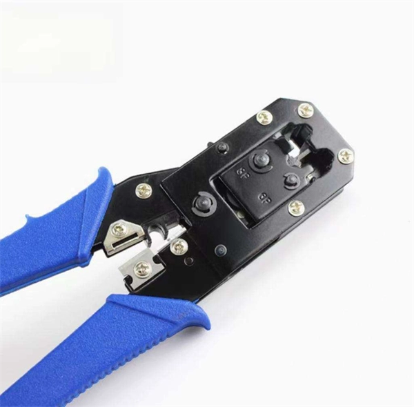
Fusion Splicer Settings – Must-Know for Fiber Technicians! 🔧 At D-TECH TRADING, we're demonstrating the essential Fusion Splicer settings that every fi. more. Auto Mode is the most intuitive and user-friendly splice mode. The fusion splicer automatically detects the fiber type, such as single-mode (SM), multimode (MM), or dispersion-shifted (DS) fibers, and adjusts parameters like arc power and heating time accordingly. Applications: Ideal for beginners. Page 1 Fusion Splicer 19R+/70R+ Quick Reference Guide Splice Operation • When splicing only standard SM fibers (ITU-T G. 652), “SM AUTO” mode is recommended. It also outlines instructions for keypad usage. st Instruction manual Fusion Splicer Please read this instruction manual carefully before operating the equipment. Adhere to all safety instructions and warnings contained in this manual. Keep this manual in a safe place. There is a change without a previous notice. We are not responsible for the. Fusion splicing is the bedrock of high-performance fiber optic networks, enabling seamless signal transmission through permanent, low-loss fiber joins. As a leading provider of fiber optic infrastructure, Weunion leverages cutting-edge tools like the AI9 and AI10 fusion splicers, paired with.
[PDF]

A Mode Conditioning Patch Cord (MCPC) is a specialized fiber patch cord designed to control the launch condition of light from a single-mode transmitter into a multimode fiber. Fiber optic cables primarily come in two types: Multimode Fiber (MMF): Has a larger core, allowing multiple light modes (paths) to travel. It's designed for short-distance, high-bandwidth applications within buildings or campuses. Common types are OM1, OM2, OM3, and OM4. Its primary purpose is to reduce differential mode delay (DMD) and prevent bandwidth limitation when legacy multimode. FS offers OM1 & OM2 mode conditioning fiber optic patch cables (MCP) in any connector & cable length, optimal for eliminating differential mode delay effects. This document describes the installation and use of the mode-conditioning patch cords listed in Table 1. 3z-compliant optical fiber assembly consisting of a single-mode fiber permanently coupled off-center to a 62. 5/125) fiber optic cable by offsetting the Singlemode Laser launch from the.
[PDF]

This is where a small but mighty hero comes into play: the Mode Conditioning Patch Cable (MCP). In this guide, we'll demystify what a mode conditioning patch cable is, why it's essential in specific network scenarios, and how it can save you from a world of connectivity headaches. This guide offers the key technical insights you need to select and install the optimal fiber optic cabling solutions for your specific needs. Covers the basics of fiber optic technology, including how light waves transmit data through thin strands of glass or plastic, and why fiber optics surpass. Fiber optic cables use light to transmit data, whereas traditional cables rely on electrical signals, which are more prone to interference and loss over distance. Connector types play a crucial. Fiber optic technology has transformed the way we transmit data, enabling faster, more reliable connections than traditional copper cables. Understanding fiber optic cable types is essential for anyone looking to build or maintain efficient fiber networks. We'll also. This is a plain-English guide for facilities and IT teams who want fiber that performs well, stays organized, and doesn't turn every add/change into a disruption. Start with the link's distance and speed, then pick single-mode (OS) or multimode (OM)—not the other way around.
[PDF]

In fiber-optic communication, a single-mode optical fiber, also known as fundamental- or mono-mode, is an optical fiber designed to carry only a single mode of light - the transverse mode. Modes are the possible solutions of the Helmholtz equation for waves, which is obtained by combining. Single-mode fiber is a specialized type of optical fiber designed to transmit light along a single, narrow path, or “mode. ” This technology is foundational to modern digital communication, enabling the high-speed transfer of massive amounts of data over vast distances. This type of fiber is used for transmitting signals over long distances. It is specified as the best for especially long-distance applications than multimode fiber. This saves space and money. Dual fiber modules use two fibers. They are easier to set up and give steady communication. It comprises one glass or plastic fiber and features a tiny core of about 8-10 microns in diameter. This. There are two main types of fiber optic cables: single mode and multimode. Although they can do the same job in some instances, the different construction methods make each of them better suited to certain tasks and budgets.
[PDF]

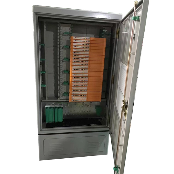
Not all splitters are created equal. Here are the main types you'll encounter: The "1×N" notation indicates one input fiber and N output fibers. A 1×2 splitter divides the signal into two outputs, while a 1×8 splitter divides it into eight. The more splits, the. By dividing a single optical signal from a central Optical Line Terminal (OLT) into multiple outputs for Optical Network Terminals (ONTs) at users' homes, splitters eliminate the need for dedicated fibers to each residence—slashing infrastructure costs while scaling network reach. This guide. A fiber-optic splitter, also known as a beam splitter, is based on a quartz substrate of an integrated waveguide optical power distribution device, similar to a coaxial cable transmission system. The optical network system uses an optical signal coupled to the branch distribution. The fiber optic. Optical couplers can split or join signals in fibers. You can connect many users to one port with 1:n or 2:n splitters. These devices work both ways, which helps strong network communication. In a Passive Optical Network (PON), a single optical fiber carries massive amounts of data using light. They are named by the number of inputs and outputs, so a splitter with one input and 2 outputs is a 1X2, and a PON splitter with one input and 32 outputs is a 1X32.
[PDF]

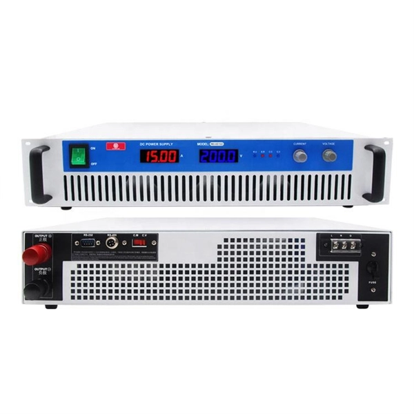
By operating from a single 2. 5V input power rail and integrating the controller, gate driver, power inductor, and MOSFETs, these mini modules are optimized for space-constrained applications like optical modules, wearables, IoT, networking. SFP (Small Form-factor Pluggable) optical modules are compact, hot-pluggable transceivers that enable network equipment to connect seamlessly to fiber and copper links. These modules, including SFP, SFP+, and SFP28, are widely used in enterprise networks, data centers, and carrier-grade deployments. The optical module serves as a crucial component in optical fiber communication systems, operating at the physical layer, which is the lowest layer in the OSI model. Its primary function is to achieve optoelectronic conversion by converting electrical signals into optical signals and vice versa. Think of it as the “translator” for your network equipment, converting electrical signals into optical signals. As an essential component of optical fiber communication, optical modules are optoelectronic devices that facilitate the conversion between optical and electrical signals during the transmission process. They are essential in applications like telecommunications, data centers, and enterprise networks. Optoelectronic devices have transmitting and receiving modes.
[PDF]

Featured with transmitting and receiving signals over a single strand of fiber, 40G and 100G BiDi transceivers have emerged as a cost-effective solution for fiber optical cable utilization and data center deployment. These two BiDi transceivers will be described in. This guide explains how bidirectional communication works in the 100G Ethernet standard to effectively double the density of your existing fiber strands. Moving to 100GbE does not have to mean a complete infrastructure overhaul. Bidirectional fiber delivers multiple practical benefits to 100G. 100G BIDI QSFP28 optical transceiver uses the wavelengths of TX1304nm/RX1309nm with PAM4 signals for up to 40km transmission over single-mode fiber. The module supports 103. 25Gb/s with PAM4 lane signaling data rate with a simplex LC connector using the QSFP28 footprint. 25Gb/s electrical-to-optical. The Cisco 100GBASE Quad Small Form-Factor Pluggable (QSFP) portfolio offers customers a wide variety of high-density and low-power 100 Gigabit Ethernet connectivity options for data center, high-performance computing networks, enterprise core and distribution layers, and service provider. However, with multiple module types—such as SR4, LR4, CWDM4, and ZR4 —each optimized for different distances, fiber types, and network architectures, selecting the right 100G QSFP28 transceiver can be challenging. The module incorporates one channel optical signal and operates on 1271nm and 1331nm wavelength.
[PDF]
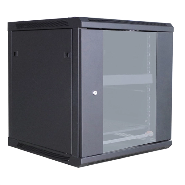
Materials $450, labor $900, permits $0–$200, total $1,350–$1,550, per-breaker costs vary, overall project time 4–6 hours. Span reflects standard new breakers and enclosure. Mid-Range: 150–200A upgrade, some rerouting, outdoor panel, weatherproof box. Distribution box cost encompasses various factors that influence the overall investment in electrical distribution systems. A distribution box serves as a crucial component in electrical installations, housing circuit breakers, fuses, and other protective devices that ensure safe power distribution. Buyers typically pay a broad range for replacing a distribution box, driven by box size, amperage, wiring runs, and local labor rates. Key cost drivers include panel amperage, indoor vs outdoor location, wiring length, and whether a full panel upgrade or rerouting is needed. The article outlines cost ranges, per-unit pricing, and practical. Wall-mount cabinet secures and organizes 4U of 19-inch rack equipment in network wiring closets and other locations with limited floor space. Houses equipment up to 20 inches deep, but extends just 8 inches from wall. SmartRack 5U Low-Profile Vertical-Moun. SmartRack 6U Low-Profile. When you start looking for a distribution box, you'll quickly realize the price range is wider than a highway. You might find a small plastic unit for the price of a fancy dinner, or an industrial-grade stainless steel beast that costs as much as a compact car.
[PDF]
The vertical clearance for overhead fiber optic lines above the highway must be a minimum of 18 feet. org The Fiber Optic Association, Inc. (FOA) was founded in 1995 to help develop the workforce to build the fiber optic networks to support a rapid expansion in communications and the Internet. The charter of the FOA was to promote professionalism. 4. FO-VC2 JOINT USE - VERICAL MIDSPAN CLEARANCES 48. FO-GB GROUNDING AND BONDING 49. FO-RI JOINT USE RISER. cations, security, control and similar purposes. It defines a minimum leve e fiber optic cabling extends between buildings. Although the standard covers premises installations, many of the provisions included here ar SI/ NFPA 70, the National Electrical Code (NEC). It is the responsibility of users. safety glasses, harness when more than 4' off gro house and pull line out to the ap g, J-hooks, drop hangers, and zip ties whe raight-line poles and 2 J-hooks when mak, around every 3rd pole, and at the last pole drop hits. For example, on a ead for mast attachments and P-hook for eve the. The plate RC. It should be plated for each cable once per station, not per foot. Field conditions will vary, so the actual location. Fiber optic cable installed in conduit shall be in accordance with the following: 132. No more than two 90 degree changes in direction per cable pull. Circuitous pulls and pulls exceeding 1000' (300 m) shall be made by back feeding or center feeding of cable.
[PDF]
This study is focused on the detailed examination of the combustion properties and kinetic analysis of a cellulose acetate fibrous bundle (CAFB), separated from used cigarette filters. Introduction Cigarette butts are the most common garbage lying in city streets, restaurants, bus stops, parks, and other public places. Although cigarette butts are small, they are. Fiber Bundles and more general fibrations are basic objects of study in many areas of mathe-matics. A fiber bundle with base space B and fiber F can be viewed as a parameterized family of objects, each “isomorphic” to F, where the family is parameterized by points in B. For example a vector bundle. In this paper, we introduce RBPseg, a method that combines monomeric 23 ESMfold predictions with a novel sigmoid distance pair (sDp) protein segmentation technique. These segments are then predicted in parallel using AF2M and assembled into a 26 full fiber model. We demonstrate that.
[PDF]