In conclusion, we have numerically analyzed the effect of higher-order nonlinearity on the spectral properties of a nonlinearly chirped fiber grating having sinusoidal cladding function profile and su.
[PDF]
A compact fiber Bragg grating (FBG)-based strain sensor has been developed by embedding an FBG inside a 3D-printed structure, allowing the comparison of FBG responses across different filaments such a.
[PDF]
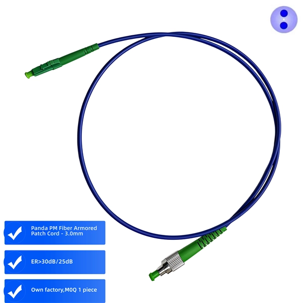
In this study, a new simulation method is proposed and verified for fiber Bragg grating patterned on polarization maintaining fiber(PM-FBG) using the transfer matrix approach. The method is designed to solv.
[PDF]
The change of both physical length and strain-dependent refractive index of the fiber, are calculated by altering the bend radius of the sensor. The detection of the bend radius is determined by the shift of the Bragg wavelength from the reflection/transmission. Fiber Bragg grating (FBG) sensors have emerged as advanced tools for monitoring a wide range of physical parameters in various fields, including structural health, aerospace, biochemical, and environmental applications. This review provides a comprehensive overview of FBG sensor technology. A variation of the period of the grating inscripted in a fiber optic – induced by mechanical or thermal perturbation – causes a shift of the reflected peak wavelength, due to the related optical path length variation. where Pij are the Pockel coefficients of the elasto-optic tensor, n is the. Optical sensors based on Fiber Bragg Gratings (FBG) are becoming increasingly popular. They are easy to install, immune to electromagnetic interferences and can also be used in highly explosive atmospheres. But just how does a fiber Bragg grating work? Our experts answer this and other questions. In the field of mechanical engineering, the accurate calculation of bending strength for spur gears is fundamental to ensuring the reliability and durability of transmission systems. The basic approach involves simplifying the gear tooth as a cantilever beam and incorporating form factor and stress.
[PDF]
stands at the forefront of innovation with its pioneering tunable fiber Bragg grating technology. Our unwavering dedication lies in crafting state-of-the-art tunable fiber optic devices and systems with diverse applications. We specialize in custom fabrication of fiber optical gratings (FBG) across wavelengths from 400 nm to 2000 nm, tailored to precise customer specifications. Using high-power laser irradiation, we permanently modify the refractive index of the fiber core, delivering FBGs with low optical loss and. Optical Gratings are optical components that consist of a periodic structure of parallel slits or grooves etched or ruled onto a substrate material. The leading manufacturers of Gratings are listed below. Narrow down on the list of companies based on their location and capabilities. Products include phase masks, fiber optics based sensor and system, partial discharge and twin grating cavity sensors. Gould Fiber Optics is estimated to have 50-99 employees. Our patented fiber. TECHNICA focuses on Fiber Bragg Gratings (FBG) based products. Implementing our Mission we deliver the highest quality, most reliable, and. Explore 16 top manufacturers and suppliers of Fiber Bragg Gratings in our comprehensive photonics buyers' guide. A fiber Bragg grating is a type of optical filter that is inscribed or "written" into the core of an optical fiber. It consists of a periodic modulation of the refractive index along the.
[PDF]
The primary application of fiber Bragg gratings is in optical communications systems. They are specifically used as. They are also used in optical and with an, or (OADM). Figure 5 shows 4 channels, depicted as 4 colours, impinging onto a FBG via an optical circulator. The FBG is set to reflect one of the channels, here channel 4. The signal is reflected back to the circulator where it is directed down and dropped ou.
[PDF]
The first in-fiber Bragg grating was demonstrated by in 1978. Initially, the gratings were fabricated using a visible laser propagating along the fiber core. In 1989, Gerald Meltz and colleagues demonstrated the much more flexible transverse holographic inscription technique where the laser illumination came from the side of the fiber. This technique uses the interference pattern of ultraviolet laser light to create the periodic structure of the fiber Bragg grating.
[PDF]

Shop DigiKey's large in-stock selection of Fiber Optic Attenuators. View inventory, pricing and order now for same day shipping!. Fiber optic attenuators are devices used to reduce or monitor the power level of a fiber optic signal. Basic types of fixed attenuation include single mode, dual window and multimode in D4/PC, FC, FC/UPC, MU, SC, SC/APC and UPC, ST and ST/UPC style connectors. Optical attenuators usually work by. FS fixed and variable fiber optic attenuators with leading attenuating fibers guarantee consistent and stable fiber attenuation (0~60dB) in WDM transmission. Thorlabs has a wide variety of single mode (SM), polarization-maintaining (PM), or multimode (MM) fixed and variable optical attenuators (VOAs). We offer SM and PM electronic VOAs that provide control of the output power with FC/PC or FC/APC connectors. Our SM and PM manual VOAs are available. Fibertronics, Inc. These attenuators are suitable for use in single mode 9/125, multimode 50/125, and multimode 62. This ensures optimal signal levels across fiber networks, preventing receiver overload and maintaining data integrity. These attenuators are essential. Attenuators are used to weaken or control a transmitted optical signal and preserve the quality of that signal when the laser or VCSEL is too strong for the receiver to read correctly. Attenuators are available in several styles and they can have either fixed levels of attenuation or they can be.
[PDF]

This practical file details experiments conducted in Optical Fiber Communication, covering modulation techniques, system components, and performance analysis. An optical fiber is a glass or plastic fiber designed to guide light along its length, widely used in fiber-optic communication, which permits transmission over longer distances and at higher data rates than other forms of communications. Fiber-optic communication is a method of transmitting. Availability of plastic optical fiber (POF) The plastic optical fiber used in some of these experiments is available for science distributors. It is a 1000micron (1mm) POF available from several suppliers. FOA has samples available at no cost for teachers at schools in the US. Key experiments include amplitude modulation, frequency modulation, and pulse width modulation, aimed at understanding fiber optic systems. This document summarizes 10 experiments on optical fiber communication: 1. Studying a 650mm fiber optic analog link and the relationship between input and received signals. Optical fiber communication Laboratory Optical fiber communication Laboratory List of Experiments: 1. To set up a analog optical fiber link 2. To measure the characteristics of LED and LASER 5. Tech curriculum designed to provide a comprehensive understanding of optical fiber communication systems. This lab offers an immersive, web-based simulator that enables you to explore and experiment with key concepts in optical.
[PDF]

The first thing you should do is locate the fiber optic cable that comes from the service provider. Once inserted, make sure it is. However, setting up a fiber optic connection to your router can seem daunting if you're unfamiliar with the process. This comprehensive guide combines industry standards with field-tested practices to ensure you achieve a rock-solid. Setting up a fiber internet connection requires understanding key hardware components and following a specific connection sequence to establish your home network. This guide details the necessary physical and digital steps to connect your fiber line and activate your internet service. The technician powers, tests, and activates the connection to confirm full speed and signal quality. * In some instances, the ONT and the router are all in the same device, generally called a combo unit. Here's a step-by-step guide to help you through it. Understand the Basics Before diving in, familiarize yourself with the components involved:. Tecnobits - Router - How to connect a fiber optic cable to the router Hello, Tecnobits! 👋 Connecting fiber optic cables to the router so that your internet flies like a spaceship! 😉 Explore with us on our website! And don't miss our latest news. See you soon! 🚀 How to connect a fiber optic.
[PDF]
Yes, you can unplug your fiber optic cable, but it's crucial to do so with extreme care to avoid damage, contamination, and service interruption. Fiber optic cables are delicate and require specific handling procedures to maintain their performance and longevity. However, situations may arise requiring you to disconnect these specialized cables from modems or routers. Fiber optic cables transmit data. Unplugging a fiber optic cable from a modem is a task that requires careful handling to avoid damaging the delicate fibers within the cable. Fiber optic cables are different from traditional copper cables, as they use light to transmit data, and the connectors are more sensitive. Is this something that requires a Verizon support tech or can I do it? If so is it as simple as disconnecting and reconnecting or would I have to call support to "reinitiate" my setup. Not my pic, but didn't feel like moving the. In this video, I'm showing you how to remove an optical fiber cable connector from a modem. This is a popular video tutorial that is often requested by viewers. This guide will help you safely and effectively remove a.
[PDF]

To use a power meter for fiber optic testing, always clean connectors first with lint-free wipes or click-to-clean tools. Select the correct wavelength and set your reference. You measure optical power in dBm or insertion loss in dB. Consistent procedures ensure accuracy. Verify light travels from. The most basic fiber optic measurement is optical power from the end of a fiber. This measurement is the basis for loss measurements as well as the power from a source or presented at a receiver. Typically both transmitters and receivers have receptacles for fiber optic connectors, so measuring the. An optical power meter measures the strength of light traveling through a fiber optic cable, giving you a reading in dBm (decibels relative to one milliwatt). This article will guide you through the methods, instruments, and key considerations for measuring fiber. Fiber optic cabling is the high-performance core of today's datacom networks. As network speeds and bandwidth demands increase, fiber performance requirements have become more stringent. Fiber testing is more important than ever. An OPM uses a photodiode to generate an electrical current proportional to optical power.
[PDF]
FC-FC Type: Commonly known as circular to circular tail fiber, typically used for jumpers between ODF racks. At the first step of phage infection, the receptor-binding proteins (RBPs) such as tail fibers are responsible for recognizing specific host surface receptors. The proper folding and assembly of tail fibers usually requires a chaperone encoded by the phage genome. Despite extensive studies on phage. Bacteriophage Mu is a temperate phage known to infect various species of Enterobacteria, playing a role in bacterial mutation induction and horizontal gene transfer. This initial binding is a fundamental step that dictates whether a phage can successfully infect a particular bacterial cell. Tail. A tail fiber, also known as a fiber optic patch cord, consists of a connector on one end and a cut end of the fiber optic cable core on the other. These patch cords are primarily used to connect fiber optic cables to fiber optic transceivers (couplers, jumpers, etc.
[PDF]

In short length cables a visual fault locator (VFL) can find where the cut is or find the bad connector at patch panels. For longer distance cables, the use of an OTDR is required. Once the fault is located, fusion splicers and splice-on connectors can be used to complete the repair. Fiber optic cables are the backbone of modern networks, delivering fast and reliable data transmission. Accidental cuts, breaks, or other damage can disrupt your network and cause costly downtime. With the right tools and techniques, you can efficiently repair damaged fiber cables and restore. Fiber optics offers advantages like EMI immunity and low attenuation (0. 2 dB/km), but it's fragile—susceptible to breaks, bends, and contamination. Repairs focus on restoring the light path with minimal signal loss (<0. A fusion. Visual inspection and specialized tools like OTDRs, OPMs, and VFLs are essential for identifying and locating physical damage or faults in fiber optic cables. Emergency restoration planning involves implementing backup power solutions, network redundancy planning, and strategies for prompt. Fiber optic cables are critical components of modern communication networks, transmitting vast amounts of data at lightning speeds.
[PDF]
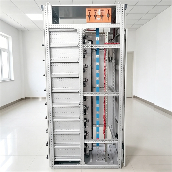
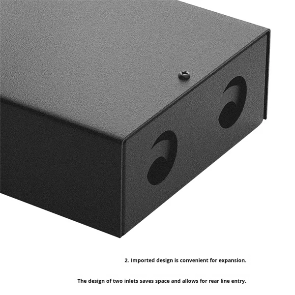
This guide provides a comprehensive engineering perspective on ODFs—beyond the basic “what is an ODF” explanation—covering structural design, fiber management, MPO/MTP integration, and selection criteria for modern high-density deployments. Why ODFs are the Foundation of. This complete guide explores everything you need to know about ODFs — from their structure, types, and key components, to installation best practices and modern design trends. Whether you're building a central office, data center, or FTTx distribution network, understanding the right ODF. In the complex architecture of fiber optic networks, the Optical Distribution Frame (ODF) serves as the linchpin for organizing, protecting, and distributing optical signals. As data centers, enterprises, telecom operators, and smart-building infrastructures deploy increasingly dense fiber links, ODFs provide the structured. An ODF is a central hub in fiber optic networks, crucial for managing and organizing the variety of fiber-optic cables and connections entering a facility such as a telco central office (CO). They provide efficient fiber optic management, connectivity, and protection. What is Optical Distribution Frame An Optical Distribution Frame (ODF) is the central hub of your fiber optic network.
[PDF]