Lighting Control System | Smart Lighting Wiring Setup | Full Guide In this video, you will learn how to connect and install a Lighting Control System step-by-step. This guide covers wiring setup, switch modules, dimming control, sensor setup and panel . as a guide for proper and reliable installation. The mounting location should e selected and prepared based on the application. All electrical wiring and mounting hardware (i. ) should be prepared with consideration of the requirements o cuit breaker before. Intelligent Lighting Controls' installation guides provide detailed instructions on how to install all of our solutions. The Lightolier Controls Optio Lighting Control Panels are high-performance, wall mounted lighting control panels which offer a wide range of dimming and relay modules to accommodate any lighting control application.
[PDF]

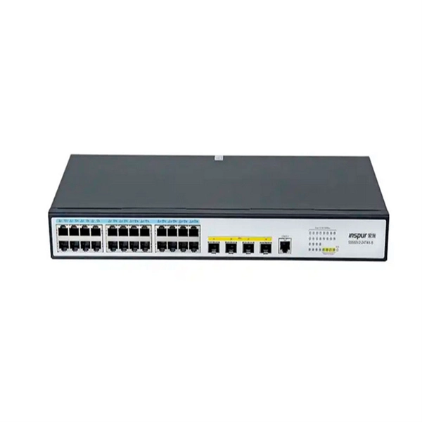
These installation instructions provide overview and specification information for small form-factor pluggable (SFP/ SFP+/SFP28) modules, as well as instructions for installing and removing the modules. Small form factor transceiver modules (including SFP, SFP+, and SFP28 modules) plug into the SFP. Some Extreme Networks switches support the use of 25 Gb SFP28 pluggable optical modules. Each module provides one 25-gigabit transmit and receive channel. Use of 25Gb SFP28 modules in QSFP28 ports requires the use of the QSFP28 to SFP28 adapter (part no. Use only Extreme Networks-certified. The ESR SFP28 module provides a 25 Gb optical connection using an LC duplex optical connector over one pair of OM3 or OM4 multimode fibers. One data lane operates in each direction, at 25 Gbps up to 200 meters using OM3 fiber or up to 300 meters using OM4 fiber. The fiber-optic SFP modules contain a laser that is classified as a “Class 1 Laser Product” in accordance. LINK-PP offers a full range of optical transceivers and SFP module for modern data centers, telecom networks, and enterprise infrastructures. Our portfolio spans data rates from 1G to 400G, including SFP, SFP+, SFP28, QSFP+, QSFP28, QSFP-DD, and OSFP modules, designed for both single-mode and.
[PDF]
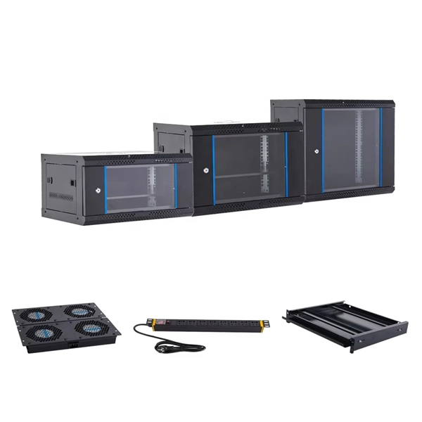
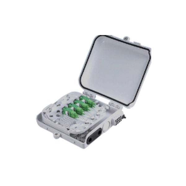
Choose the right box based on environment (indoor/outdoor), load capacity, and durability. Check for proper IP/NEMA ratings and material quality. Ensure safe placement: install in dry, accessible areas with good ventilation and at appropriate height (typically ~1. In this guide, we'll break down everything you need to know to install a distribution box correctly and confidently. Necessary materials include an electrical enclosure, expansion bolts, fixing brackets, screws, terminal blocks, qualified wires, cable ties, insulating tape, etc. Inspect all of them. This video provides valuable insights for anyone looking to improve their electrical wiring skills and ensure safe and reliable power distribution. In modern electrical systems, cable distribution boxes (also known as electrical distribution boxes or distribution boxes) play a crucial role as the key hub for managing, distributing, and protecting circuits. Whether it is residential buildings, commercial facilities or industrial sites, the. A distribution box, also known as a distribution board, electrical panel, or breaker box, is an enclosure that houses electrical components responsible for distributing electricity throughout a building. It serves as a central hub for distributing electricity throughout a building, ensuring that power is delivered safely and efficiently to all the required locations.
[PDF]
This video shows real on-site footage of electrical installation, demonstrating safe and standardized wiring methods used by professionals. Whether in a home or an industrial facility, this box keeps your electrical setup organized, functional, and efficient. However, the key to a safe and reliable system lies in proper installation. If it's done poorly, you risk short circuits, fire hazards, or system failure. Done right, it ensures. Whether you are an electrical contractor or a construction brigade, knowing how to properly and safely install distribution boxes is the basis of ensuring the safe operation of the entire system. This article details the process of installing them, which helps you comprehend distribution boxes. How to Install a Cable Distribution Box Safely and Correctly? In modern electrical systems, cable distribution boxes (also known as electrical distribution boxes or distribution boxes) play a crucial role as the key hub for managing, distributing, and protecting circuits. Can I convert the circuit wiring in my shop to be used for different equipment? Converting Existing Circuit Wiring in a Workshop or Garage. There is a demand for more RCD protection of final circuits, affect Type B MCB distribution boards and their protective d bar arrangement designed to accept single and/or double pole OCPDs.
[PDF]
A distribution box is the heart of any electrical system. It takes the incoming power and safely distributes it to different circuits throughout your building. Whether in a home or an industrial facility, this box keeps your electrical setup organized, functional, and efficient. However, the key to. A well-chosen and properly installed distribution box can prevent electrical hazards, reduce downtime, and ensure your electrical system operates smoothly for years to come. Let's explore how these critical components work and why they deserve your attention. A distribution box, also known as a. A distribution box, also known as a power distribution box or electrical distribution box, is used to distribute electrical power safely to multiple circuits. This article details the process of installing them, which helps you comprehend distribution boxes. stallation and use of boxes. The article includes table references that guide the electrician in the selection of the proper box size necessary to safely accommodate ele trical service requirements. The box capacity table shown (page A-5) is reproduced in part from the NEC® as a quick reference and. Electrical layouts, wiring diagrams, and installation plans. every one of these technical documents relies on clear and consistent visual representations of electrical symbols. And for a project to run smoothly, everyone on your team needs to speak the same visual language used in those documents.
[PDF]
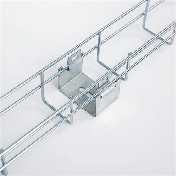
Calculate cable tray fill ratio, weight loading, and derating factors for multi-standard compliance. This calculator features an interactive interface with advanced visualizations. Open the full calculator for the best experience. IEC 61537 covers cable tray and cable ladder systems for the support and accommodation of cables, while NEC Article 392 governs cable. Article Summary: A compliant cable tray installation requires a thorough understanding of NEC Article 392, proper structural support, and precise installation techniques. This guide covers the critical steps, from selecting the right electrical cable tray and performing accurate cable fill. Properly sizing your cable tray is critical for safety and compliance. Follow these simple steps: Define Tray Dimensions: Enter the width and depth of your planned cable tray (in mm or inches). Save your cable tray sizing calculator results as branded PDF. A 12 in ladder tray loaded to 4 in depth has 48 sq in of tray area; with 24 #12 THHN conductors at 0. 0133 sq in each, the screen is about 0. This page is a preliminary cable-tray occupancy screen for early layout work. It adds cable planning area, compares. This publication is intended as a practical guide for the proper and safe* installation of cable ladder systems, cable tray systems, channel support systems and associated supports. Cable ladder systems and cable tray systems shall be manufactured in accordance with BS EN 61537, channel support.
[PDF]
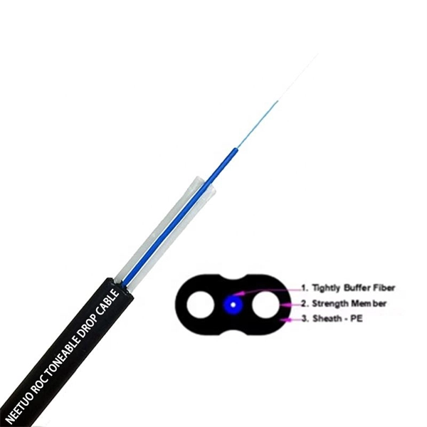
Fiber optic cable installation costs between $1,500 and $7,000 for your home, with prices varying by cable length and installation method. The installation type you choose and the layout of your property determine the total labor and materials needed for your project. How Much Does Fiber Optic Installation Cost Per Foot? Cable Material Costs: Installation Costs by Method: Prices can range from $1 to $50+ per linear foot depending on the method and complexity. The initial cost of installing fiber optic cables can vary depending on the chosen installation method. Home and business fiber optics projects typically range from a few hundred to several thousand dollars, depending on run length, fiber type, and labor needs. This. Whether you're running fiber to a home or a data center, here's exactly what contractors are charging in 2026. What is the real cost of fiber optic cable per foot in 2026? After analyzing 40+ U. fiber projects, we've assembled current material rates, labor burdens, and hidden fees. You should account for permit. If you're grappling with the complexities of budgeting for fiber optic installations 1, understanding the cost dynamics of single-mode fiber optic cables 2 is crucial. The price per foot includes the fiber itself, connectors, and basic installation factors, with main drivers being cable type, distance, and any required conduit or termination hardware. This article outlines cost expectations.
[PDF]
Find out the design of robust cable tray installation in pump stations. This manual includes elements such as material choice, cables with heavy loads of the motors, and grounding as a way of providing long-term reliability. This procedure to clear the method of the supply, installations Cable Tray and Trunking System for the project. Delivery and inspection upon arrival of material at site. Installation of the. No description has been added to this video. Enjoy the videos and music you love, upload original content, and share it all with friends, family, and the world on YouTube. Below is the detailed cable tray installation method statement not only for cable tray but also applicable for GI ladder and trunking for indoor and outdoor applications and in service rooms like pump rooms, electrical rooms and plant rooms etc. All materials intended for cable tray, ladder and. Variations of types of armored cables as found by Variable Frequency Drives (VFDs) are much heavier than regular wires. When the tray is too weak, it will bend and may result in dangerous power failure. When electricity is passed through big cables, they become hot. The plastic covering may melt. association representing the major electrical equipment manufac-turers in the U. QA/QC : Quality Assurance / Quality Control Engineer. MIR : Material.
[PDF]

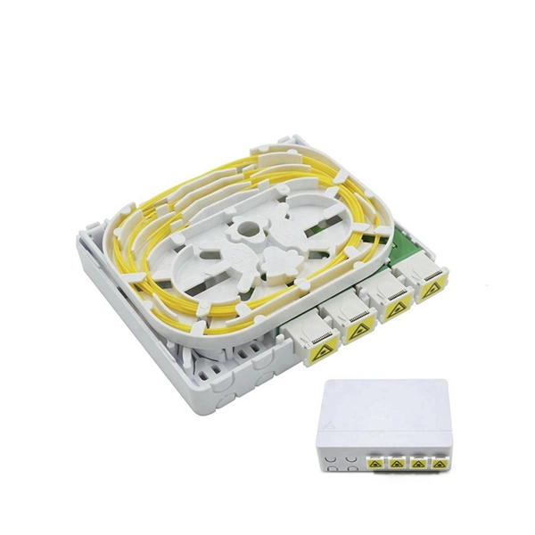
These networks rely on optical fibers, which are thin strands of glass or plastic that carry light signals. The ONU serves as the termination point of a fiber-optic network, converting the optical signals back into electrical signals for distribution to end-user devices. A GEPON system usually consists of an OLT (Optical Line Terminal) at the service provider's central office and multiple ONU (Optical Network Units) or ONT (Optical Network Terminals) close to the end user as optical splitters. In addition, the transmission between OLT and ONU/ONT adopts an optical. In the realm of Fiber-to-the-Home (FTTH) and other FTTx architectures, the Optical Network Unit (ONU) is a critical piece of customer-premises equipment (CPE). The primary function of an. ONU stands for Optical Network Unit. Think of it as. ONU (Optical Network Unit) plays a crucial role in modern telecommunications, enabling seamless connectivity and high-speed data transmission across fiber optic networks. As global demand for Fiber-to-the-Home (FTTH) expands, ONUs have become essential for delivering reliable broadband to homes. As an essential node in Passive Optical Networks (PON), the ONU not only handles the conversion between optical and electrical signals but also supports various services such as data, IPTV, and voice. This article will provide a detailed explanation of the working principles of ONUs and their.
[PDF]

Bit Error Rate (BER) is a critical performance metric in optical communications that measures the number of errors occurring in a transmitted data stream over a certain period. It is defined as the ratio of the number of bits received in error to the total number of bits transmitted. This ratio is most often expressed using scientific notation (e., 10⁻⁸. USI has industry-leading capabilities in high-speed signal integrity and power integrity (SI/PI) design, as well as advanced thermal simulation and optical simulation using Zemax. In addition, we have strong expertise in high-speed PCB design utilizing mSAP and substrate PCB technologies. USI also. Unlock AI-driven, actionable R&D insights for your next breakthrough. As optical links are increasingly used for high-speed data. Even a digital data transmission system is not totally error-free — statistical fluctuations related to noise influences cause a small percentage of the transmitted bits to be corrupted. The average fraction of incorrectly transmitted bits is called the bit error rate. Offers precise, cost-efficient optoelectronic signal and anomaly testing for high-speed transceivers. · Use control board and replaceable.
[PDF]

Its typical transmission distance is 20km or 40km. For instance, some ethernet switch manufacturers refer to the 1000BASE-LH SFP as the 1G 1310nm 40km SFP transceiver, which indicates the module's transmission distance and wavelength. The 10G SFP+ dual-fiber optical module is a small pluggable optical transceiver that adopts a dual-fiber bidirectional design. It completes signal transmission (Tx) and reception (Rx) through two independent optical fibers, ensuring the stability and reliability of signal transmission. An SFP (Small Form-factor Pluggable) module transmits data over fiber using specific wavelengths and power levels, which directly influence how far the signal can travel before degradation occurs. This is why two. If the optical module works at a wavelength near 850nm (880nm) or 910nm (940nm), then the module is a multi-mode fiber (MMF) optical transceiver, and if the working wavelength is 1310nm or 1550nm, it is a single-mode fiber (SMF)optical module. Generally, the maximum transmission distance(generally. The transmission distance of optical transceiver modules is divided into short distance, medium distance, and long distance. A 1-core module uses a single fiber core for data transmission, while a 2-core module uses two cores. o Think of a highway. Chromatic dispersion This is a key factor affecting single mode fiber distance.
[PDF]

In simple terms, Receiver Sensitivity is the minimum received optical power required at the input of a receiver for the system to achieve a specified performance level, typically defined by a maximum Bit Error Rate (BER). Think of it like listening to a distant radio station. The standards body governing the application sets this specified BER. For example, SONET specifies that the BER must be 10 -10 or better. Optical modules form the backbone of modern data center networks, enabling ultra-high-speed data transmission between servers, switches, and storage devices. In optical link design, the receiver performance parameters are like vital signs of the link, directly determining the reliability and. Receiver sensitivity shows the weakest signal your device can find. Good sensitivity gives stronger connections, even with weak signals. Always look at the dBm value in product details. A lower dBm means better receiver sensitivity. This helps you pick the best device. It denotes a module's capability to function in challenging environments and aids network operators in determining the system's maximum reach or link margin.
[PDF]

Traditional pluggable optical modules are approaching their physical limits in three core dimensions: power consumption control, signal integrity and port bandwidth density. Low Latency: LPO technology eliminates the need for a DSP, reducing a processing step and thus lowering data transmission latency. This advantage is particularly important in high-performance computing (HPC) scenarios, where minimizing latency is a key factor in achieving optimal performance. By. Among the emerging technologies, LPO (Linear Pluggable Optics), NPO (Near-Packaged Optics), and CPO (Co-Packaged Optics) represent three important stages in the evolution of next-generation data center optical networking. Understanding how these architectures differ is essential for designing. Optical communications are emerging as the next AI computing infrastructure frontier, driven by data interconnection bottlenecks. Lumentum's order book is full through 2028, reflecting surging demand for 800G and 1. 6T optical modules, amplified by Nvidia's strategic investment., May 4, 2026 – GlobalFoundries (Nasdaq: GFS) (GF) today announced the introduction of its SCALE™ optical module solution for co-packaged optics (CPO). GF's SCALE. In Feb. 2023, the State Council issued the "Overall Layout Plan for Digital China Construction. ” It proposes six key tasks,including enhancing the efficient.
[PDF]

Usually, the 10G/25G grey light optical modules with a short transmission distance are applied for connecting AAU/DU with WDM/OTN/SPN. The connections between WDM/OTN/SPN network devices can be achieved by 10G/25G/50G/100G dual-fiber or single-fiber bidirectional. Compared with Draft A (2013-07-30), this issue includes the following new topic: 2. This section describes engineering specifications of an AAU, including input power and equipment specifications. 7. In 2/3/4G networks, 10Gbps optical modules are generally enough for CPRI interfaces. In 5G networks, CPRI is also upgraded to eCPRI. Currently, 5G of the bearer network mainly uses 25Gbps optical modules. Next, ETU-LINK will introduce the types of optical modules used by 10G SFP+ and 25G SFP28. What is the difference between the 5G bearer network and the traditional optical transmission network? The main difference is that 5G fronthaul needs to support CPRI/eCPRI protocol. Most of the AAU of 5G base stations are deployed outdoors. In order to resist harsh environments such as high. The optical modules used to connect BBU and RRU devices are optical modules and optical fibers. Product Versions The following table lists the product versions related to this document. 25G SFP optical module adopts the wavelength of 850nm, with an operating.
[PDF]
This manual describes Inspect, a command-line tool for debugging TNS C/C++, COBOL, FORTRAN, Pascal, Screen COBOL, and TAL programs and snapshots on HP NonStopTM TNS/R and TNS/E systems. MFT (Mellanox/NVIDIA Firmware Tools) is a set of firmware management utilities for querying firmware details, performing firmware upgrades, and other configuration tasks. It includes four main components: mst, mlxburn, flint, and Debug Utilities. For full specifications, refer to the official. All commands were tested on HP/Aruba 5400 switches (specifically 5406Rzl2), but will work on any model with recent firmware versions (16. x or newer), except for the hardware features unavailable on smaller models, like VSF. This publication supports J06. 03 and all subsequent J-series RVUs, H06. Show general info: current CPU load, uptime, memory used/free, software. The HP 1-Port 1GbE Flex IO NIC is designed to work in the Flex IO port of select HP systems. Refer to platform specifications for compatibility. It utilizes a Realtek RTL8153 10/100/1000 Ethernet controller to provide an additional 1GbE LAN Port. 3az-2010, also known as Energy. HPE Insight Diagnostics is a hardware diagnostic tool. To start iLO with keyboard and monitor connected to the box - press F8 while booting Invoke virtual serial port. Starting text console. Press 'ESC (' to return to the CLI Session.
[PDF]
