This handbook covers the code of practice in protection circuitry including standard lead and device numbers, mode of connections at terminal strips, colour codes in multicore cables, dos and donts in execution. Also principles of various protective relays and schemes including special protection. Read this document and the documents listed in the additional resources section about installation, configuration, and operation of this equipment before you install, configure, operate, or maintain this product. Users are required to familiarize themselves with installation and wiring instructions. presentation of protection and control relaying. The report will identify methodology behind these practices, present issues raised by the integration of microprocessor relays and the internal logic and external communication configurations, ying. The objective of this presentation is to convey a basic understanding of protective relays to an audience of engineers already familiar with low voltage protective device coordination. HT panel protection relay. The HT power supply is received from GO switch and distributed to the. The handbook for protection engineers includes guidelines on protective circuitry, protective relay principles, and testing procedures for switchgear and relays. It covers standard codes, wiring practices, and norms for protecting generators, transformers, and lines, and provides detailed.
[PDF]
Read the topics and perform the procedures in this order: 1. Preparing for Installation 2. Planning a Switch Data Stack 3. Installing and Removing an SFP and SFP+ Module 6. Where To. The following information is for FCC compliance of Class A devices: This equipment has been tested and found to comply with the limits for a Class A digital device, pursuant to part 15 of the FCC rules. These limits are designed to provide reasonable protection against harmful interference when the. What Can I Do If a Message Is Displayed Indicating that an Optical Module Is Not Supported During Stack Port Configuration? - S300, S500, S2700, S5700, and S6700 V200R023C00 Configuration Guide - Device Management - Huawei How Do I Install a License File for a Stack System? How Do I Specify a. Page 1 Catalyst 3650 Switch Hardware Installation Guide April 2016 Cisco Systems, Inc. com Cisco has more than 200 offices worldwide. Addresses, phone numbers, and fax numbers are listed on the Cisco website at www. Text Part Number: OL-29734-01. Page 2 OR ITS. This guide describes the hardware features of the Catalyst 3650 switches. It describes the physical and performance characteristics of each switch, explains how to install a switch, and provides troubleshooting information. This guide does not describe system messages that you might receive or how.
[PDF]
At the heart of every optical transceiver lie three essential components, often called the “Three Pillars” of optical communication: Laser — generates light. Modulator — encodes data onto the light. Photodiode — decodes light signals back into electrical form. An optical receiver is a device that converts light signals traveling through fiber optic cable back into electrical signals that electronic equipment can process. The core function of the optical receiver relies on a physical phenomenon known as photoelectric conversion. When a modulated light signal. The polarization independent isolator is made of three parts, an input birefringent wedge (with its ordinary polarization direction vertical and its extraordinary polarization direction horizontal), a Faraday rotator, and an output birefringent wedge (with its ordinary polarization direction at. Our optical receivers and detectors make photodetection easy and provide the lowest noise and cleanest response possible. Our broad offering spans wavelength ranges from UV to short-wave IR for free-space and fiber-coupled configurations in many versions: high-speed, general-purpose, balanced. Optical receivers are devices that convert light signals into electrical signals using photodetectors, which come in various types such as photodiodes and avalanche photodiodes. The document covers key concepts such as the operating principles of these detectors, noise types, signal-to-noise ratio.
[PDF]
Our Passive FTTH fiber optic receiver is an essential component for bringing fiber access to households. It is designed for use in FTTH (fiber-to-the-home) networks, enabling analog or digital signal acces.
[PDF]

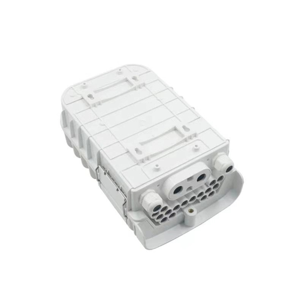
In modern FTTH architectures, the ODN is the physical fiber layer that distributes optical signals from the central office to end users. Operators consider ODN design as one of the most important factors affecting: Network coverage Optical loss performance Deployment cost. This passive layer is known as the Optical Distribution Network (ODN). Its role is to provide an optical transmission channel between the OLT and the ONU. The ODN network design is a physical facility that connects the communication room and user equipment, and is a key component. Short summary: The Optical Distribution Network (ODN) is the passive infrastructure linking the central office to the subscriber in FTTH. This guide delves into essential ODN components like splitters, distribution boxes, and ODFs, showcasing how Hainan ZTO Cable Co. It's the silent, robust highway that delivers blazing-fast Fiber-to-the-Home (FTTH) and 5G services. The maximum permissible optical power attenuation between OLT optical ports to ONT input is 28dB, which is by utilizing the so-called Class B optical network. At the heart of every Fiber-to-the-Home (FTTH) deployment lies the Optical Distribution Network (ODN) — a meticulously engineered passive infrastructure that enables operators to deliver massive bandwidth, low latency, and reliable service to millions of users. The ODN connects the Optical Line.
[PDF]
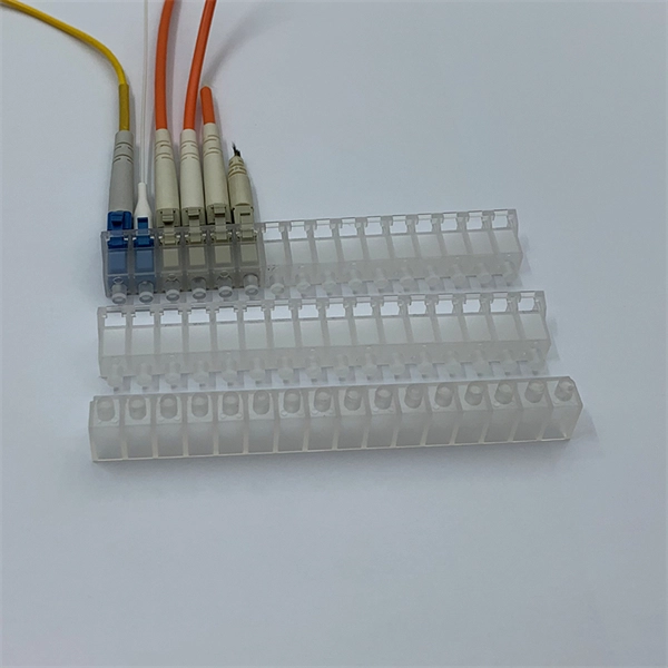
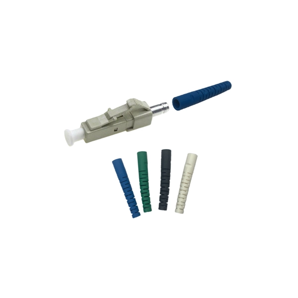
In this guide, you will find a chronological description of the fusion splicing process, the principal technical standards, and answers to the real-life questions network engineers and procurement teams may have. What is Fiber Optic Splicing and Why is it Needed? – #1. Use and Maintain Your Cleaver Correctly – #3. Set Your Fusion Parameters in a Systematic Way What is Fiber Optic Splicing and Why is it Needed? First, let us understand the meaning of the term. Fiber optic splicing, crucial for maintaining seamless connectivity in modern communication networks, primarily uses two methods: fusion splicing and mechanical splicing. Therefore, we will also touch on cost factors, risk management, and best practices in. This is where fiber optic cable splicing—the process of creating a permanent, high-performance join between two fiber ends—becomes critical. For network managers and technicians, a poor splice can lead to significant signal degradation, network downtime, and costly troubleshooting. At Turn-Key. Fiber optic cable splicing connects two cables, creating a strong link for fast data transmission. Splicing fiber helps light signals move easily, ensuring your internet connection remains reliable. Another method of connecting optical fibers is termination or connectorization, which consists of processing the end of a fiber optic bundle so that it can be connected to other fibers or devices through fiber optic.
[PDF]

Explore verified suppliers, compare prices from $183–$2,500, and discover top-rated products with 16 port capacity, GPON compatibility, and customizable options. Click to find the best fit for your network needs. We use cookies or similar technologies to ensure this website functions properly, analyze traffic, or optimize your experience. Continuing to browse this site indicates your agreement to use these cookies. Learn More Tenda Optical line terminals, also called optical line terminations (OLTs), serve. At the heart of a point-to-multi-point or passive optical network (PON) is the optical line terminal (OLT). Modern OLTs offer communication service providers (CSP) the ability to launch multigigabit services to tens of thousands of subscribers from a single location or just ten. Fiber-to-the-home. FlexSym Optical Line Terminal Two (OLT2) The Tellabs FlexSym® OLT2 Optical Line Terminal is a multi-purpose Optical Line Terminal (OLT) enabling open, simple, and scalable connectivity for wired and wireless networks over fiber and copper networks. Our silicon devices have been interoperability-tested, field-proven and adopted by various worldwide operators and carriers. 2065 olt ftth optical line terminal products are offered for sale by suppliers on Alibaba. com, of which fiber optic equipment accounts for 85%. Explore our range of high-quality GPON, EPON, and XG (S)PON OLT products.
[PDF]
An optical line termination (OLT), also called an optical line terminal, is a device which serves as the service provider endpoint of a passive optical network. It provides two main functions: to perform conversion between the electrical signals used by the service provider's equipment and the fiber optic signals used by the passive optical network.to coordinate the multiplexing between the conversion. FeaturesOLTs include the following features: • A downstream frame processing means for receiving and churning an cell to generate a downstream frame, and converting a parallel dat. Most vendors integrate an entire fiber optic management system for ISPs to manage OLTs as well as client ONTs and as such are not interoperable. • • BT-PON.
[PDF]

ODN provides the optical transmission channel between OLT and ONU. Each ONU analyzes the signal transmitted from the ODN, extracts the portion intended for that ONU, and schedules user information to send back via the ODN. The Passive Optical Network (PON) is the indispensable foundation for delivering ubiquitous, multi-gigabit broadband connectivity, a necessity for modern economies and residential life. The shift from outdated electrical copper systems to optical fiber is driven by the immutable demands for. PON (passive optical network) is a fiber-optic network that employs a point-to-multipoint topology and fiber optic splitters to transmit data from a single source to multiple user endpoints. In contrast to AON, multiple customers are connected to a single transceiver by means of. A GEPON system usually consists of an OLT (Optical Line Terminal) at the service provider's central office and multiple ONU (Optical Network Units) or ONT (Optical Network Terminals) close to the end user as optical splitters. This network is distinguished by its capability to make the data transmission from a single source to multiple user terminals. While both devices are essential in a Passive Optical Network (PON) setup, they serve entirely different.
[PDF]
Instantly reprogram, test, and unlock universal compatibility for every optical module — with full diagnostics and OTA updates built in. It lets you check the health of any SFP or QSFP module and program them effortlessly in seconds. We're cutting prices across the entire Ubiquiti SFP lineup — up. SFPTotal devices are full-compatible with official software SFPTotal Wizard which provides a convenient interface that allows to read, decode, edit and write changes to the memory of optical transceivers GBIC, SFP, SFP+, SFP28, XFP, QSFP+, QSFP28 and QSFP-DD form factors. Copy or write optical module profiles instantly. MFT (Mellanox/NVIDIA Firmware Tools) is a set of firmware management utilities for querying firmware details, performing firmware upgrades, and other configuration tasks. It includes four main components: mst, mlxburn, flint, and Debug Utilities. For full specifications, refer to the official. Reprogram and Diagnose Optical Modules Instantly with SFP Wizard The Ubiquiti UACC-SFP-Wizard is a portable, all-in-one optical module programmer and diagnostic tool designed for IT.
[PDF]

In this guide we will be going over how to configure multiple VLANs with routing so that each VLAN has Internet access. Configuring Multiple VLANs with Internet Access. The decision on using IP routing and VRF routing in the core switch is a design choice that can provide performance advantages on inter VLAN routing within each VRF and the GRT. Moving all the VLANs to the firewall with the FW performing inter VLAN routing also within a single VRF or GRT makes the. Our Firewall is on our Data vlan and has a port on our VOIP vlan for Voice Traffic. If that helps at all, if not then we are going to need more information about your setup to be able to help. If your core switch is a layer 3 device then clients on a given subnet would have a. Routing on firewall or core switches? Hello, In my assignment I have to design a network with following components: Configuration: ● Both of the firewalls should be in cluster (HA) ● Both ISP's should be in active-passive mode with dependency with the firewall cluster. ● Each device (server. This document provides campus networks typical configuration examples and feature typical configuration examples. "Campus Networks Typical Configuration Examples" provides typical campus network networking modes and a variety of deployment examples. The slot is used to install various function modules and interface modules. We will be using a M4300-8X8F as the core switch with two M4250-8G2FX-PoE+ switches.
[PDF]
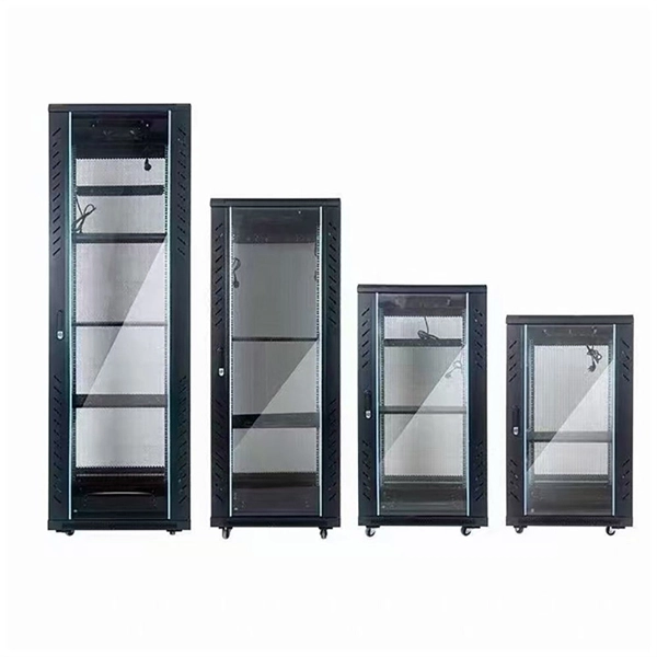
The enclosure is made of bent steel plates, featuring a compact structure, easy maintenance, and flexible circuit scheme combinations. Besides air circuit breakers and fuses for circuit protection, the distribution cabinet can also be equipped with contactors and thermal relays. Mauritius power strips and PDU power distribution units for surface mount, rack mount and general purpose applications. Multiple outlet power strips are manufactured in accordance to Mauritius standards with agency approvals. Designed for safety and durability, our range includes solutions for residential, commercial, and industrial electrical setups in Mauritius. Practibox S surface mounting cabinet with earth terminal blocks -. Mauritius is one of the world's most renowned island destinations, attracting millions of visitors each year with its tropical beaches, luxury resorts, and vibrant tourism industry. Behind the smooth operation of hotels, restaurants, and resort facilities lies a critical requirement: stable and. The transmission and distribution system forms the backbone of electricity supply in Mauritius, ensuring reliable power delivery from generation facilities to customers across the island. How the System Works Electricity is transmitted at higher voltages from generation sources to Bulk Supply. The XL type low-voltage power distribution cabinet uses domestically designed new components. The answer lies in upfront. Meta Description:.
[PDF]