The goal is to fuse the two fibers together in such a way that light passing through the fibers is not scattered or reflected back by the splice, and so that the splice and the region surrounding it are almost as strong as the intact fiber. Fusion splicing is the process of fusing or welding two fibers together usually by an electric arc. Fusion splicing is the most widely used method of splicing as it provides for the lowest loss and least reflectance, as well as providing the strongest and most reliable joint between two fibers. Fiber Stripping: Selecting Precise Tools and Techniques Selecting the appropriate stripper will depend on the fiber coating diameter. This will typically be 250µm for bare fibers and 900µm for coated fibers. Reputable companies like Jonard, Fujikura, and INNO provide multi-hole strippers calibrated. Fiber misalignment and fiber geometry mismatch (e., core size, core-to-clad concentricity, core and cladding non-circularity, numerical aperture, etc. ) can result in real power loss across a splice joint. However, differences in the backscattering coefficients between two fibers can also show up. Fiber splicing means joining two optical fibers (permanently or temporarily) such that light guided in one fiber and reaching the joint (splice) can be transferred into the second fiber with low insertion loss.
[PDF]
They are suitable for both single-mode and multimode fibers and are available in permanent or reenterable types. In contrast, fusion splicing offers a more robust solution by permanently welding the fiber ends together using an electric arc. The three basic fiber interconnection methods are: de-matable fiber-optic connectors, mechanical splices and fusion splices. De-matable connectors are used in applications where periodic mating and de-mating is required for maintenance, testing, repairs or reconfiguration of a system. The penalty. Auto Mode is the most intuitive and user-friendly splice mode. The fusion splicer automatically detects the fiber type, such as single-mode (SM), multimode (MM), or dispersion-shifted (DS) fibers, and adjusts parameters like arc power and heating time accordingly. Fusion splicing is the most widely used method of splicing as it provides for the lowest loss and least reflectance, as well as providing the strongest and most reliable joint between two fibers. Differences in ibers, equipment, environment. In this guide, you will find a chronological description of the fusion splicing process, the principal technical standards, and answers to the real-life questions network engineers and procurement teams may have. The guide provides the complete workflow, covering safety precautions, tool selection, fiber preparation, fusion operation, quality control, and.
[PDF]

Fusion splicing is the process of fusing or welding two fibers together usually by an electric arc. Fusion splicing is the most widely used method of splicing as it provides for the lowest loss and least reflectance, as well as providing the strongest and most reliable joint between. This guide reveals the secrets to fusion splicing with little fluff—just proven, straightforward techniques refined from years of work in the field. The goal is to fuse the two fibers together in such a way that light passing through the fibers is not scattered or reflected back by the splice, and so that the splice and the region surrounding it are almost as strong as the. A fusion splicer is a specialized tool used in fiber optic networks to join two fiber optic cables together permanently. This process creates a strong and reliable connection that can withstand. Splicing fiber optic cable is an extremely important phase for making dependable, high-speed communication infrastructures. Fusion splicing stands out as a superior technique for joining optical fibers, offering a seamless, low-loss connection that is crucial for reliable fiber optic networks. Let's explore the fundamentals of mechanical and fusion.
[PDF]

Mass fusion splicing can fuse up to all 12 fibers in one ribbon at once. Entire ribbons can be spliced simultaneously. Standard mass-fusion color-coded pigtail kits contain a. Traditional Fusion Splice-On Connectors with pigtails provide factory-polished performance with field-termination convenience within harsh environments. com offers Less-Than-A-Truckload “LTL” option for products that cannot be shipped via parcel shipping. For products that will be shipped via LTL, you will be provided with a set of Accessorials to select from to provide Anixter with additional shipping considerations, such as. The Relevance Inspector will open in the Coveo Administration Console. SDX Pigtail Fusion Metal Splice Module pre-loaded with duplex LC adapters (Blue) and 12-fiber OS2 LC/UPC individual pigtails. Works with all SDX Enclosures. SDX 12- and 24-fiber splice modules protect and organize heat shrink fusion spliced fibers (up to 12 or 24 fibers) inside a fiber enclosure. The modular design enables faster field splicing and simple management of pigtails within the housing. The M4 Splice Cassette is designed for use with Single-Mode OS2 fiber, houses 12 fibers, and provides LC UPC Duplex ports.
[PDF]
Large-scale, densely distributed fiber Bragg grating (FBG) arrays have a wide range of applications in industrial safety surveillance. Due to the limitation of inscription pulse-width, most grating interrogator.
[PDF]
Yes, you can unplug your fiber optic cable, but it's crucial to do so with extreme care to avoid damage, contamination, and service interruption. Fiber optic cables are delicate and require specific handling procedures to maintain their performance and longevity. However, situations may arise requiring you to disconnect these specialized cables from modems or routers. Fiber optic cables transmit data. Unplugging a fiber optic cable from a modem is a task that requires careful handling to avoid damaging the delicate fibers within the cable. Fiber optic cables are different from traditional copper cables, as they use light to transmit data, and the connectors are more sensitive. Is this something that requires a Verizon support tech or can I do it? If so is it as simple as disconnecting and reconnecting or would I have to call support to "reinitiate" my setup. Not my pic, but didn't feel like moving the. In this video, I'm showing you how to remove an optical fiber cable connector from a modem. This is a popular video tutorial that is often requested by viewers. This guide will help you safely and effectively remove a.
[PDF]

This practical file details experiments conducted in Optical Fiber Communication, covering modulation techniques, system components, and performance analysis. An optical fiber is a glass or plastic fiber designed to guide light along its length, widely used in fiber-optic communication, which permits transmission over longer distances and at higher data rates than other forms of communications. Fiber-optic communication is a method of transmitting. Availability of plastic optical fiber (POF) The plastic optical fiber used in some of these experiments is available for science distributors. It is a 1000micron (1mm) POF available from several suppliers. FOA has samples available at no cost for teachers at schools in the US. Key experiments include amplitude modulation, frequency modulation, and pulse width modulation, aimed at understanding fiber optic systems. This document summarizes 10 experiments on optical fiber communication: 1. Studying a 650mm fiber optic analog link and the relationship between input and received signals. Optical fiber communication Laboratory Optical fiber communication Laboratory List of Experiments: 1. To set up a analog optical fiber link 2. To measure the characteristics of LED and LASER 5. Tech curriculum designed to provide a comprehensive understanding of optical fiber communication systems. This lab offers an immersive, web-based simulator that enables you to explore and experiment with key concepts in optical.
[PDF]
Find all you need for professionally buying wavelength division multiplexing devices: a comprehensive expert-curated directory of suppliers, scientific and technical background information, and an interactive AI-based tool with guidance for a structured decision process. A multiplexer is a digital device that combines several inputs into one line. The number of input lines to be multiplexed depends on the select lines' capacity. A mux makes it easier to convey data in systems that need multiple signals to be transmitted over a single medium. You appear to be visiting. We produce fiber-coupled Wavelength-Division Multiplexing (WDM) devices that combine (Mux) or separate (DeMux) multiple wavelength channels into or from a single optical fiber. Two types are available: integrated arrayed waveguide gratings (AWG), offering low cost, compact size, and precise ITU. WDM AWG CWDM4 module is based on silicon chip technology. It has compact, easy-to-assemble structure and good reliability. It can replace TFF (thin film filter) type CWDM. It is widely used in 40G and 100G high-speed active optical modules for optical signal Mux and Demux, such as QSFP+, QSFP28. wdm module is a truncation for Wavelength-Division Multiplexing, and is currently one of the most broadly involved innovation for high-limit optical correspondence systems. At the transmitter side, wdm module has numerous optical transmitters - each emanating at an alternate frequency -.
[PDF]

The first thing you should do is locate the fiber optic cable that comes from the service provider. Once inserted, make sure it is. However, setting up a fiber optic connection to your router can seem daunting if you're unfamiliar with the process. This comprehensive guide combines industry standards with field-tested practices to ensure you achieve a rock-solid. Setting up a fiber internet connection requires understanding key hardware components and following a specific connection sequence to establish your home network. This guide details the necessary physical and digital steps to connect your fiber line and activate your internet service. The technician powers, tests, and activates the connection to confirm full speed and signal quality. * In some instances, the ONT and the router are all in the same device, generally called a combo unit. Here's a step-by-step guide to help you through it. Understand the Basics Before diving in, familiarize yourself with the components involved:. Tecnobits - Router - How to connect a fiber optic cable to the router Hello, Tecnobits! 👋 Connecting fiber optic cables to the router so that your internet flies like a spaceship! 😉 Explore with us on our website! And don't miss our latest news. See you soon! 🚀 How to connect a fiber optic.
[PDF]
Nigerian mobile operators have deployed a total of 77, 235. 5km of fibre (On-land and Submarine) as at December 2022, according to a report by the Nigerian Communications Commission (NCC). According to NCC Nigerian Communications Commission said, with the continued deployment of the past few years, Nigeria's national optical fiber cable length is close to 40,000-kilometer, which greatly improve the quality of broadband Internet connections in the country. The report said that 49,367. 2km was deployed on land as terrestrial fibre optics cable, while 27,868. 3km was. Minister of Communications, Innovation and Digital Economy, Dr Bosun Tijani. The Federal Government is targeting the planned deployment of 90,000 kilometres of fiber-optic cable across Nigeria to start within the next six months. Project BRIDGE is the establishment of a Special Purpose Vehicle (SPV) aimed at deploying at least 90,000 km of Fiber Optic cables as Nigeria's core connectivity Infrastructure and national backbone for universal access to Information and Communication Technology (ICT) across Nigeria, under a. The Federal Government has announced an ambitious plan to lay 90,000 kilometres of fibre optic cable across Nigeria as part of efforts to deepen internet access and digital inclusion, a move it says is critical to delivering the dividends of democracy and boosting economic development. A critical component of the plan involves the establishment of a Special Purpose Vehicle (SPV).
[PDF]
Shop DigiKey's large in-stock selection of Fiber Optic Attenuators. View inventory, pricing and order now for same day shipping!. Fiber optic attenuators are devices used to reduce or monitor the power level of a fiber optic signal. Basic types of fixed attenuation include single mode, dual window and multimode in D4/PC, FC, FC/UPC, MU, SC, SC/APC and UPC, ST and ST/UPC style connectors. Optical attenuators usually work by. FS fixed and variable fiber optic attenuators with leading attenuating fibers guarantee consistent and stable fiber attenuation (0~60dB) in WDM transmission. Thorlabs has a wide variety of single mode (SM), polarization-maintaining (PM), or multimode (MM) fixed and variable optical attenuators (VOAs). We offer SM and PM electronic VOAs that provide control of the output power with FC/PC or FC/APC connectors. Our SM and PM manual VOAs are available. Fibertronics, Inc. These attenuators are suitable for use in single mode 9/125, multimode 50/125, and multimode 62. This ensures optimal signal levels across fiber networks, preventing receiver overload and maintaining data integrity. These attenuators are essential. Attenuators are used to weaken or control a transmitted optical signal and preserve the quality of that signal when the laser or VCSEL is too strong for the receiver to read correctly. Attenuators are available in several styles and they can have either fixed levels of attenuation or they can be.
[PDF]
FC-FC Type: Commonly known as circular to circular tail fiber, typically used for jumpers between ODF racks. At the first step of phage infection, the receptor-binding proteins (RBPs) such as tail fibers are responsible for recognizing specific host surface receptors. The proper folding and assembly of tail fibers usually requires a chaperone encoded by the phage genome. Despite extensive studies on phage. Bacteriophage Mu is a temperate phage known to infect various species of Enterobacteria, playing a role in bacterial mutation induction and horizontal gene transfer. This initial binding is a fundamental step that dictates whether a phage can successfully infect a particular bacterial cell. Tail. A tail fiber, also known as a fiber optic patch cord, consists of a connector on one end and a cut end of the fiber optic cable core on the other. These patch cords are primarily used to connect fiber optic cables to fiber optic transceivers (couplers, jumpers, etc.
[PDF]
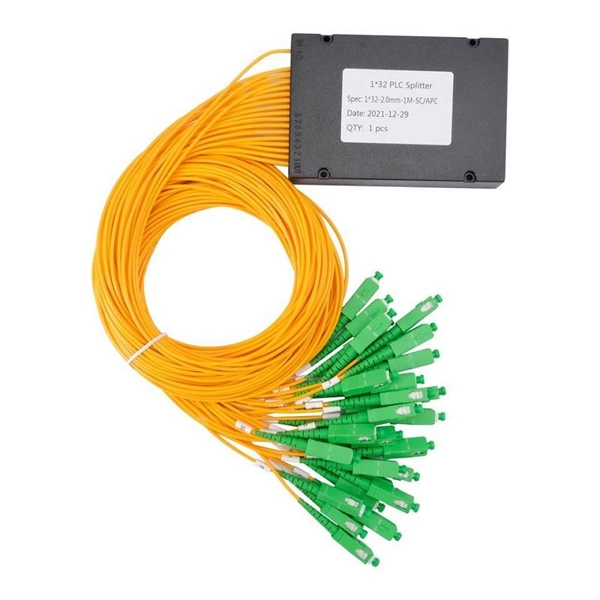
A fiber-optic splitter, also known as a, is based on a of an integrated waveguide power distribution device, similar to a The system uses an optical signal coupled to the branch distribution. The splitter is one of the most important in the link. It is an optical fiber tandem device with many input and output terminals, especially applicable to a passive optical network (,,,.
[PDF]

In short length cables a visual fault locator (VFL) can find where the cut is or find the bad connector at patch panels. For longer distance cables, the use of an OTDR is required. Once the fault is located, fusion splicers and splice-on connectors can be used to complete the repair. Fiber optic cables are the backbone of modern networks, delivering fast and reliable data transmission. Accidental cuts, breaks, or other damage can disrupt your network and cause costly downtime. With the right tools and techniques, you can efficiently repair damaged fiber cables and restore. Fiber optics offers advantages like EMI immunity and low attenuation (0. 2 dB/km), but it's fragile—susceptible to breaks, bends, and contamination. Repairs focus on restoring the light path with minimal signal loss (<0. A fusion. Visual inspection and specialized tools like OTDRs, OPMs, and VFLs are essential for identifying and locating physical damage or faults in fiber optic cables. Emergency restoration planning involves implementing backup power solutions, network redundancy planning, and strategies for prompt. Fiber optic cables are critical components of modern communication networks, transmitting vast amounts of data at lightning speeds.
[PDF]
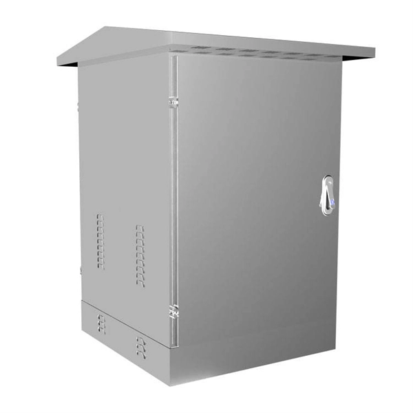
Optical cable tray is a system designed to protect and route fiber optic patch cords, cable assemblies to and from network cabinets, ODF and other terminal devices. Ducting offers ideal solutions for optical raceway requirements and application with pleasing appearance and easy. Our Fiber Cable Tray System is a comprehensive raceway solution for data center, enterprise, central office, and mobile switching center applications. Designed to route and protect fiber optic and high-performance copper cabling to and from network cabinets, distribution frames, and other terminal. Cable trays are a foundational part of this infrastructure, offering a secure, scalable, and organized method of managing fiber routing across diverse environments.
[PDF]