
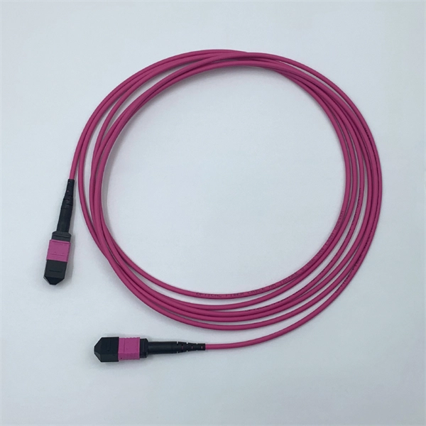
FiberMall MPO16 APC Y Splitter Cables 10m are designed for 800G QSFP-DD/OSFP DR8/OSFP XDR8 optics direct connection and support 800G transmission for Hyperscale Data Centers. Multimode PLC Splitter is a passive optical device used to split incoming signals into two or more output signals. They're capable of operating over a broad wavelength range from 650 nm to 1350 nm (Typ. 650nm, 850nm and 1300/1310nm). 5/125 (OM1, OM2, OM3 and. High-Quality Construction: This Fiber Optic PLC Splitter is manufactured by UT-KING, a reputable brand known for its reliable products, ensuring a durable and long-lasting performance. Optimized for FTTH Solutions: Designed for use in Fiber-to-the-Home (FTTH) applications, this 1x2 OM3 PLC Splitter. Optical coupler is an optical device that combines or splits power from optical fibers. Note: All insertion loss and insertion loss referenced without connectors. Takfly, established in 2000, has been manufacturing. Optional split ration 1:99, 2:98, 5:95, 10:90, 20:80. USource OM3 Fiber Coupler is a 1x2 or 1x3 passvie optical multimode splitter based on FBT (Fused Biconic Taper) technology, packaged in mini ABS box module or steel tube, split into different rations 1:99, 2:98, 50:50, 10:90, 20:80.
[PDF]
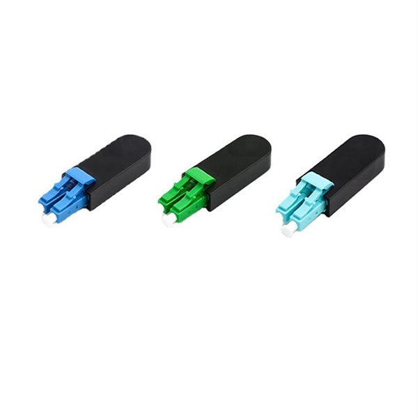
Fiber optic couplers are optical devices that connect three or more fiber ends, dividing one input between two or more outputs, or combining two or more inputs into one output. The device allows the transmission of light waves through multiple paths. These connectors combine the compact form factor of a standard duplex LC with a rugged, waterproof housing, delivering high-performance optical links that withstand rain, dust, temperature. Fiber optic adapters, also known as couplers, play a crucial role in fiber optic networks by providing a connection point between two fiber optic connectors. They enable seamless and reliable optical signal transmission between different fiber optic cables, connectors, or devices. In this tutorial. A fiber coupler is a passive optical device that manages the flow of light signals within an optical network. Directional 2 × 2 couplers (see Figure 1) are usually used for such purposes. This article explores the function, types, and applications of fiber.
[PDF]

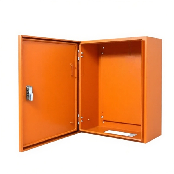
Follow a step-by-step process: mark the location, drill holes, insert anchors, and secure the box for a weatherproof fit. Apply weatherproof sealant around the box edges and cable entry points to prevent water ingress. Installing an electrical box on an exterior wall can seem daunting, but with the right guidance, it can be a straightforward task. Whether you are adding an outdoor outlet for convenience or setting up lighting, understanding the process is key. This guide will walk you through the essentials of. An electrical junction box is a protective housing designed to enclose and shield electrical wire connections or splices. For outdoor installations, the box must defend these sensitive splices against moisture, dust, temperature fluctuations, and physical impacts. Safety remains crucial during installation. It takes the incoming power and safely distributes it to different circuits throughout your building. Whether in a home or an industrial facility, this box keeps your electrical setup organized, functional, and efficient. Whether adding a GFCI outlet for safety or upgrading an exterior outlet for weather-resistant durability, it's essential to follow proper electrical wiring. In this video, I'll show you how to install a weatherproof outdoor electrical box — safe, secure, and code-compliant.
[PDF]
An electrical pigtail is a short piece of wire used to connect an electrical device, such as a switch or receptacle, to the main circuit conductors within a junction box. It acts as a jumper between the device terminal and the spliced bundle of circuit wires. This technique ensures the device is. Are a pigtail and a jumper wire the same thing, how are they different ? A jumper connects two devices or terminals together. Like you can jumper the top and bottom halves of a duplex receptacle if the bridge gets broken off. You can. The most intuitive difference between the two is that only one end of the pigtail has a connector, and both ends of the jumper have a connector. Optical Fiber Jumper: also known as optical fiber connector, both ends have connectors. Similar to coaxial cable, but without mesh shielding, for jumper. This detailed guide will take you through the basics of jumper wires, their types, applications, and the step-by-step process of connecting them securely and effectively. What Are Jumper Wires? Jumper wires are insulated wires used to connect two points in a circuit. They usually come with. Pigtails play a crucial role in ensuring safe and efficient connections within electrical systems, especially when dealing with multiple wires or limited space. Understanding what a pigtail is and how it works can make your wiring projects smoother and safer.
[PDF]
This guide covers the essential tools and step-by-step procedures for low-loss fiber optic cable repair. This complete guide covers everything from identifying causes of failure to advanced repair techniques, drawing on the latest industry standards and innovations. Whether you're a network technician, IT professional, or telecom operator, you'll find practical steps, tools, and tips to restore. This article covers the typical steps required to repair and/or re-terminate a damaged fiber optic cable. The actual steps may vary depending on the cable and/or connectors. Fiber optic cables are typically damaged in one of two ways: A premade fiber optic cable suffers connector damage when too. With the right tools and techniques, you can efficiently repair damaged fiber cables and restore reliable performance. Adhering to precise methodologies, we can mend impaired cables. While a cut or damaged fiber optic cable can temporarily take your network down, it is possible to quickly fix the cable with the right tools. This wikiHow article will teach you how to splice a cut fiber optic cable back together with a fiber optic stripper and cutter and a fiber optic crimper. To do this, you can use an OTDR, Optical Time Domain, Reflectometer. This is a testing device that looks at optical signals in the cable which can identify irregularities in the structure.
[PDF]

This article will provide an in-depth analysis of outdoor cable types, key selection criteria, core installation steps, critical precautions, as well as subsequent testing and maintenance guidelines, helping you build a robust and durable outdoor optical communication link. Therefore, understanding the characteristics of outdoor fiber optic cables and mastering proper installation methods is crucial. Plan your outdoor fiber installation carefully by surveying the site, choosing the right cable type, and following FOA and OSP standards to ensure reliability. In this video, we'll walk you through the process of establishing a robust outdoor fiber connectivity solution. Follow our guide and establish a r. more Welcome to. Running a cable through an exterior wall can be a daunting task for many homeowners, but with the right tools and techniques, it can be done efficiently and safely. With the increasing demand for high-speed internet and reliable networking, it's essential to know how to properly install CAT 6 cables outdoors. In this article, we'll take you.
[PDF]
The normal recommendation for fiber optic cable is the minimum bend radius under tension during pulling is 20 times the diameter of the cable (d). This includes pulling tension, minimum bend radius or diameter and crush loads. Installers must understand these specifications and know how to install cables without. Fiber optic cable bend radius is a critical mechanical parameter that determines how sharply a cable can be bent without risking microbending, macrobending, signal loss, or long-term structural fatigue. Proper bend radius control ensures the integrity of optical performance and protects the glass. Fiber optic cables have revolutionized communication networks, providing extremely fast data transmission through pulses of light traveling along thin glass fibers. However, these slim cables often need to twist and turn during infrastructure builds and maintenance. So an important question arises:. Ignoring the minimum bend radius for fiber optic cable can result in signal loss, increased attenuation, and long-term reliability issues. Have a network installation project? What's The Bend Radius of Fiber Optic Cables? The bend radius of fiber cables. Always keep the fiber optic cable bend radius at least 20 times the cable diameter during installation and 10 times after installation to prevent damage and signal loss. Use bend-insensitive fiber optic cables in tight spaces to reduce signal loss and allow sharper bends, but still follow.
[PDF]
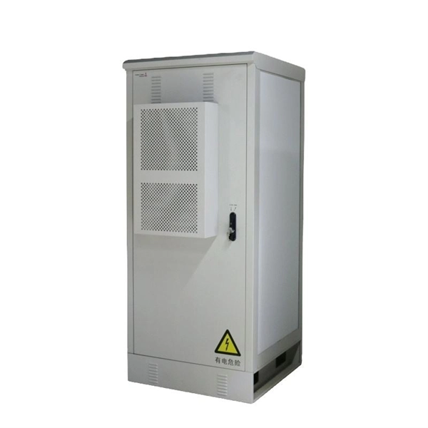
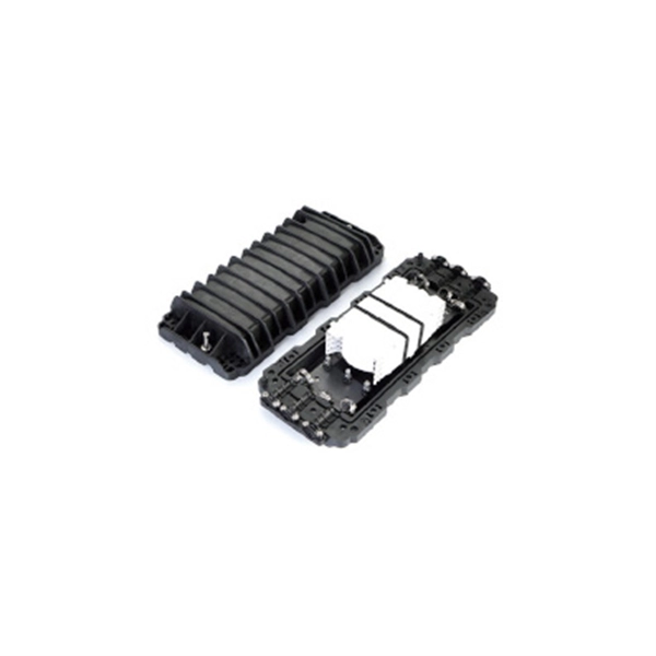
Designed for plug-and-play installation, this outdoor optical distribution box reduces on-site splicing, shortens deployment cycles, and improves installation consistency across large-scale ODN projects. It is ideal for outdoor FTTH and FTTx access networks requiring rapid. The Outdoor Optical Distribution Box (SP-GTS-B08) is a pre-connectorized FTTH access solution engineered for fast and efficient last-mile fiber deployment. Every enclosure is built at our facility in Strafford, Missouri, using U. -sourced components wherever. Protect your fiber with Amphenol FOP's rugged outdoor enclosures-IP67-rated, wall- and pole-mount with integrated cable strain relief and corrosion-resistant design. Outdoor fiber distribution box offer a variety of features that make them ideal for managing fiber optic networks. Here are some of the key features: Outdoor fiber distribution box is designed to withstand harsh environmental conditions such as extreme temperatures, humidity, and physical shock. With the changing seasons presenting new challenges for your fiber optic network to overcome, Primus Cable offers Outdoor Fiber Distribution Boxes that are designed and manufactured to endure harsh environmental conditions. Our Fiber Distribution Boxes are specially built to accommodate various. For all of your outdoor fiber distribution needs, Fiber Savvy offers an excellent solution. Easily connect your SC or LC adapters.
[PDF]
This test station do the auto-testing on 12 core (24 core) for insertion loss and return loss, highly efficient multi-core fiber insertion and return loss measurement and make high precision on the measurement result with OTDR mandrel free technical adopting. (MPO/MTP) mandrel free insertion loss test station is specially design for multi fiber testing. It combines three. •Compact benchtop instrument for all-in-one operation optic components quickly and accurately. The system has a or LED source for multi-mode applications. With a dual two wavelengths in less than 1 second. ILM-100 system comes integration into test systems. the measurement result with OTDR mandrel free technical adopting. Automatically complete the 12-core (24-core) dual-wavelength IL&RL test. The application of OTDR winding-free technology has greatly improved the insertion. You can make an inquiry about this product. Your e-mail will not be leaked.
[PDF]
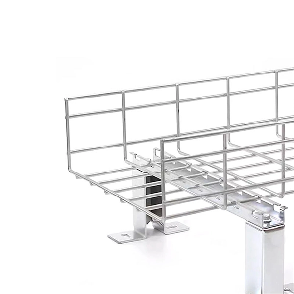
We deliver custom-made cable trays to meet the needs of your project, ensuring easy installation and reliable support for your cables. The nVent CADDY Wire Basket Tray System is an industry leading continuous pathway support solution for today's high-performance cabling systems. This robust. See our products in a new more user-friendly way We have wire trays, data racks and all accessories you need to install your cables in an easy, fast and high qualitative way. Nordic Wire Tray becomes Nordic Wire Tray. New name, new look, same Nordic quality We continue to drive innovation in cable. How can we improve? Choose from our selection of wire trays, including over 850 products in a wide range of styles and sizes. Same and Next Day Delivery. ShowMeCables stocks a range of cable management, low voltage wire holders including Duct, Spools, D-Rings, Grommets, Lacing Bars and Strips, Neat-Patch, Wall-Mounted, Vertical, Horizontal, Cable Tray and Cable Tray Accessories. Brands include ShowMeCables, L-com, ICC, Middle Atlantic, Panduit, Hosa. Count on Monosystems to deliver products, solutions and expertise that are tailor-made for the market you serve. For over 50 years, we have dedicated ourselves to providing Industry with best in class wire management solutions and to helping solve mission critical issues. Discover the benefits of each system to make an informed decision tailored to your specific application. We also offer a wide range of accessories in all.
[PDF]
Get the wrong connector type, the wrong polish, or skip proper fusion splicing technique—and you're looking at elevated signal loss, increased back reflection, and a field termination that fails certification. Thoracostomy tubes are indicated for management of air or fluid in the pleural cavity. Pigtail catheters have emerged as an effective and less morbid alternative to traditional large bore chest tubes for evacuation of pleural air or fluid. However, they do not come without complications which. Traditionally large-bore tube thoracostomy has been the standard of care for treating many acute intrathoracic pathologies. However, the advent of less invasive small-bore chest tubes, also known as pigtail catheters, has gradually led to a paradigm shift. They are used to treat a variety of conditions including pneumothorax, pleural effusion, and postoperative evacuation of air and fluid. There are a number of types and sizes of chest tubes available ranging. Return loss is the ratio of signal power injected from a source compared to the amount that is returned or reflected back toward the source. It is a critical performance parameter in both copper twisted pair and fiber optic cabling systems, because it can interfere with the transmitted signal and. Executive Summary: A fiber optic pigtail is one of the most commonly specified yet least understood components in structured cabling.
[PDF]

Mixing singlemode and multimode pigtails in the same link is a common and costly mistake. The core diameters (9 µm vs. 5 µm) are fundamentally incompatible—attempting to splice or connect them results in massive insertion loss (often 10+ dB) that will fail every optical power. Fiber optic pigtails play a critical role in modern optical networks, serving as the interface between optical fibers and active or passive devices through fusion splicing. Among the various options available, singlemode fiber pigtails and multimode fiber pigtails are the two most widely used. Choosing between single-mode and multimode fiber optic pigtails is one of the most important decisions in network design. These differences determine which transceivers work with which fiber and how far signals can travel. Understanding the compatibility constraints prevents costly downtime and troubleshooting. Choosing the right pigtail directly impacts signal transmission distance. So what's the cause of mix-using multimode and single-mode fiber? As we see, the optics applied in point-to-point interconnection are symmetrical. For instance, end A with a 10G SFP+ port houses a 10GBASE-SR SFP+ module.
[PDF]

Optical return loss is the amount of light that is reflected back to the source, this reflected light is measured at each connector and splice at each point over the entire fiber link. This is always measured in dB (decibels) and will be displayed as a negative number. The closer the number is to. The polish of a singlemode fiber endface plays a significant role in reflectance. Understand what you need before you specify. The Institute of Electrical and Building the ORL story Electronics Engineers (IEEE) recently Within a fiber-optic channel or path-released new specifications within way. Optical Return Loss (ORL) in fiber optics refers to the amount of light that is reflected back toward the source in a fiber link. ORL is usually expressed in decibels (dB) as a positive value, with. Return loss (RL) is also called reflection loss. When high-speed signals enter or exit a part of an optical fiber, such as an optical fiber connector, discontinuity and impedance mismatch may cause reflection, which is the return loss of an optical fiber. Poor ORL is commonly caused by dirty connectors, poor splices, mismatched connector types, or damaged fibers. ORL is measured using ORL meters. Home Coherent Optics Optical Return Loss (ORL) Explained Comprehensive Guide to Understanding and Managing Back-Reflections in Fiber Optic Systems What is Optical Return Loss (ORL)? Optical Return Loss (ORL) is a critical parameter in fiber optic systems that quantifies the amount of light.
[PDF]

The typical specification range of return loss of a fiber connector is -15 dB to -60 dB. Return loss is also known as reflection loss. It indicates the amount of signal reflected back to the transmitting end. Return loss refers to the power loss caused by the reflection of part of the signal back to the signal source during transmission due to the discontinuity of the transmission. Insertion loss, also known as attenuation, is the loss of optical power that occurs when light passes through a fiber optic connector. It is caused by factors such as misalignment, air gaps, and imperfections in the connector components. The lower the insertion loss, the better the performance of. Reflectance (which has also been called "back reflection" or optical return loss) of a connection is the amount of light that is reflected back up the fiber toward the source by light reflections off the interface of the polished end surface of the mated connectors and air. It is also called. Insertion Loss (IL) is the amount of optical power lost as the signal travels from one point to another in a fiber optic link, usually across connectors or splices. Formula for. In optical fiber communication, insertion loss and return loss are two important parameters to evaluate the quality of interfaces between some optical fiber components, such as optical fiber connector, fiber patch cable, pigtail fiber, etc. While it's natural to have.
[PDF]

Single-mode optical modules are best for long distances and fast speeds. They use a thin fiber core. Whether you're designing a short-range data center network or a long-distance metro backbone, understanding the distinctions between single vs. dual fiber and single-mode vs. This guide breaks down these two critical dimensions of optical transceiver design to help. Choosing between Single Mode and Multimode Optical Modules will shape cost, reach and upgrade paths. This guide breaks down practical differences—core geometry, wavelengths, connector types, performance limits, cost trade-offs, and ideal use-cases—so you can pick the right optical modules with. Optical modules are core photoelectric conversion components in fiber-optic communication, data centers, enterprise networks, and telecom transmission systems. Here are some methods you can use: Single-mode (SM): Typically has a smaller core diameter, usually around 9 microns. Singlemode and multimode SFP modules are two primary categories of hot-swappable optical modules used in optical networks. Each module type uses LC interfaces, and professionals commonly group them together under the name LC SFP modules. They mainly differ in the type of optical fiber they operate.
[PDF]
