Fiber optic networks offer superior performance and bandwidth compared to traditional copper-based networks. In this step-by-step guide, we'll show you how to build a high-speed fiber optic network using 2 fiber switches. Check the model number of your shiny new switch. Or, if you are using a spare, check the device. Two fiber optic cables are required between each pair of fiber switch modules. Use a high quality duplex fiber optic cable containing 62. 5/125 or 50/125 multimode fiber or g/125 for single mode fiber. Use ST. Anixter is your source for Switches products. PromoTech stands out as a trusted provider, offering high-performance networking switches and essential accessories to support seamless connectivity and operational efficiency across the island. The resource has not been reviewed by Editors yet. Readers are advised to use their best judgement. We are experts in the field of Fiber Optic Design; Installations, Splicing, Testing, Maintenance and Training with highly trained and certified personnel. Our team can integrate the use of Fiber Optics into any “Greenfield” or existing network, on small, medium or large enterprise projects both.
[PDF]
Run the loopback-detect untagged mac-address ffff-ffff-ffff command in the system view to broadcast BPDUs for loopback detection and prevent them from being terminated by unexpected devices. Huawei's comprehensive portfolio of products and solutions enables you to realize smooth digital transformation and rapid growth of virtualization, Big Data, and cloud services. Huawei switches already help customers achieve success in industries such as finance, Internet, retail, education. Plan the network configurations, configure loop prevention protocols, and enable loopback detection to prevent loops. They provide ultra-high-density 10GE/40GE/100GE/200GE/400GE full-rate access ports, meeting customers' requirements for quickly building campus networks with a simplified. CloudEngine S12700H series switches are Huawei's next-generation modular core/aggregation switches designed for high-end campus networks in the all-wireless era of Wi-Fi 6/7. CloudEngine S12700H series switches come in two models, which offer four and eight LPU slots, respectively. The S9700 uses an advanced multilayer switching architecture to support sustained bandwidth upgrading and to provide 40GE. This document provides campus networks typical configuration examples and feature typical configuration examples. "Campus Networks Typical Configuration Examples" provides typical campus network networking modes and a variety of deployment examples.
[PDF]

Built on Huawei's unified software platform and equipped with high-performance fully programmable chips, they deliver abundant features including Service Roam, VXLAN and iFlow, helping customers build high-quality campus bearing networks for the all-wireless era. Leveraging the Service. CloudEngine S5735-S-V2 switches support simplified operations and maintenance (O&M), and flexible Ethernet networking. It also provides enhanced Layer 3 features and mature IPv6 features. For example, it can be used as an access or. CloudEngine S5736-S series switches are next-generation standard all-optical GE access switches that provide 24-port and 48-port models, and provide four 10GE ports and one extended slot(optional). CloudEngine S5736-S series all-optical GE access switches are developed based on next-generation. Comprehensive analysis of Huawei's revolutionary optical switch innovations for 2025, including data center all-optical switching, silicon photonics integration, quantum-compatible switches, and 5G-Advanced network solutions. The port supports the PoE function. It sends and receives service data at 1000 Mbit/s or 10 Gbit/s.
[PDF]
Huawei MA5683T is an aggregation Optical Line Terminal (OLT), it supports up to 6 service slots and can support a maximum of 12,000 subscribers (GPON). MA5683T has GICF/X2CS Uplink Board available for selection, and two power slot redundancy for DC power input. Ethernet link aggregation increases link bandwidth by bundling multiple physical links to form a logical link. Link aggregation can work in manual mode or Link Aggregation Control Protocol (LACP) mode. In manual mode, you must manually create an Eth-Trunk and add member interfaces to the Eth-Trunk. As shown in Figure 1, SwitchA and SwitchB are connected to the networks of VLAN10 and VLAN20, respectively, via Ethernet links, and there is a large amount of data traffic between SwitchA and SwitchB. Link aggregation has the following advantages:. Original operating mode: Two S5700s were configured with Eth-Trunk1, and the ports of the three lines that need to be communicated were added to Eth-Trunk1. Set the port to access to allow the corresponding VLAN to pass; so that the two floors of the network can communicate normally In this way. And there are two link aggregation types. In LACP mode, there are active and backup links and backup links are used for redundancy. For this example, we. Link Aggregation is a technology defined in IEEE 802. It enhances bandwidth, provides fault tolerance, and allows load balancing between connected devices. Key benefits of link aggregation: Higher.
[PDF]

In this guide we will be going over how to configure multiple VLANs with routing so that each VLAN has Internet access. Configuring Multiple VLANs with Internet Access. The decision on using IP routing and VRF routing in the core switch is a design choice that can provide performance advantages on inter VLAN routing within each VRF and the GRT. Moving all the VLANs to the firewall with the FW performing inter VLAN routing also within a single VRF or GRT makes the. Our Firewall is on our Data vlan and has a port on our VOIP vlan for Voice Traffic. If that helps at all, if not then we are going to need more information about your setup to be able to help. If your core switch is a layer 3 device then clients on a given subnet would have a. Routing on firewall or core switches? Hello, In my assignment I have to design a network with following components: Configuration: ● Both of the firewalls should be in cluster (HA) ● Both ISP's should be in active-passive mode with dependency with the firewall cluster. ● Each device (server. This document provides campus networks typical configuration examples and feature typical configuration examples. "Campus Networks Typical Configuration Examples" provides typical campus network networking modes and a variety of deployment examples. The slot is used to install various function modules and interface modules. We will be using a M4300-8X8F as the core switch with two M4250-8G2FX-PoE+ switches.
[PDF]
Since there are no feeder interconnections, a fault will interrupt all downstream customers until it is repaired. This configuration is called a radial system and is common for low-density rural areas where more.
[PDF]

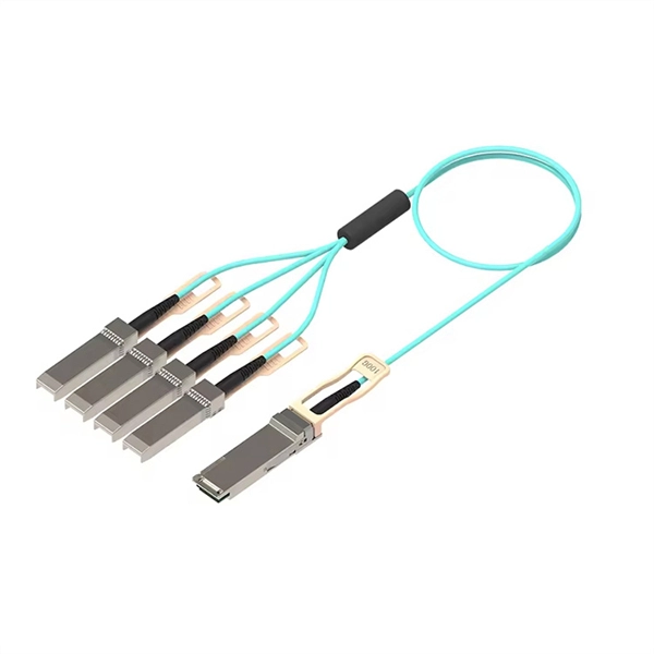
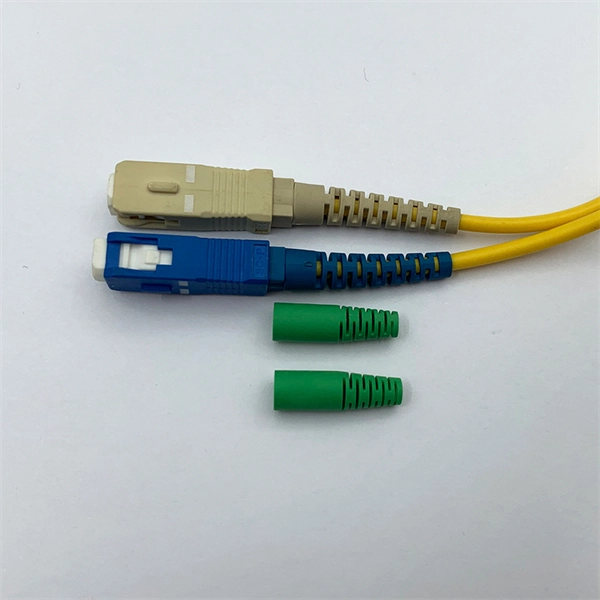
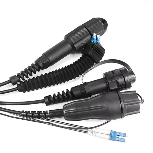
Q1: Can I plug a fiber optic cable directly into an RJ45 port? A: No. They are incompatible. Use a media converter or an SFP-based device. Many people ask the same question: Can you use a fiber optic cable with an RJ45 port? The short answer is no - RJ45 connectors are designed for electrical Ethernet signals, while fiber optics transmit light pulses through glass or plastic. However, modern networks often combine both technologies. Ethernet ports are designed for copper cables (like Cat5e or Cat6), which transmit data using electrical signals. You need a media converter or a. Connecting a switch to a fiber optic network involves several steps and requires specific equipment to ensure a successful and efficient connection. Fiber optic technology is widely used in networking due to its high-speed data transmission capabilities and long-distance coverage. Fiber provides: Increased internet signal bandwidth. Most modern fiber-enabled network switches require an SFP transceiver module. Fiber optic connectors are critical components that facilitate the seamless integration of fiber optic cables with network switches and other networking equipment. These connectors serve as the interface between the delicate optical fibers and the active components of the network infrastructure.
[PDF]
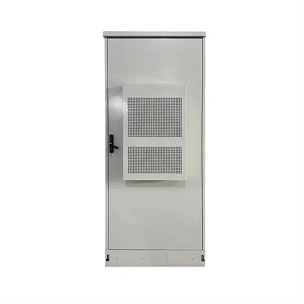
In part two of the 7-part series on how to wire a switch, I explain and demonstrate how to install the cables into a multi-gang box. The video focuses on steps that will both save time and simplify the process. In this video, we'll walk you through the process of wiring a home distribution box with a detailed connection diagram. Whether you're an electrician or a DIY enthusiast, this guide will help you understand the basics of home electrical distribution. Part of my job as a professional electrician is keeping my work neat and organized. A tidy work box makes it easier to install lights, switches, and outlets, and it helps future electricians to see what's going on inside the. Learn how to install a distribution box safely and correctly. Covers wiring, placement, standards, and expert tips for a compliant setup. A distribution box is the heart of any electrical system. It takes the incoming power and safely distributes it to different circuits throughout your building. If you're looking to install a switch box in your home or office, it's important to understand the process involved and the key steps to follow. And all the switching and protective devices are installed in the. According to NEC (National Electric Code: Article 1 00-Definitions), a Main Panel (also known as Panelboard, load center, breaker box and distribution board etc. ) is a cabinet or cutout box which contains on controlling and protective devices (such as circuit breakers, fuses, switches etc.
[PDF]
Arrangement order: The circuit breakers should be arranged from left to right, and the reserved position is generally placed on the right side of the distribution box. Distribution board is a safe system designed for house or building that included protective devices, isolator switches, circuit breaker and fuses to safely connect the cables and wires to the sub circuits and final sub circuits including their associated Live (Phase) Neutral and Earth conductors. Take the appropriate rating of MCB and RCCB as per your load requirements. Identify the Input and Output sides of the MCBs and RCCBs. If you use. In this video, we'll walk you through the process of wiring a home distribution box with a detailed connection diagram. more Welcome to our channel! In this video. A distribution box, also known as a distribution board, electrical panel, or breaker box, is an enclosure that houses electrical components responsible for distributing electricity throughout a building. It receives power from the main electrical supply and divides it into separate circuits, each. Location determination: Determine the installation position of the circuit breaker according to the position of the circuit breaker installation hole on the box cover. It serves as a central hub for distributing electricity throughout a building, ensuring that power is delivered safely and efficiently to all the required locations.
[PDF]

Main Switch: This switch controls all electricity coming into the box. Busbar: A metal strip spreads power to each circuit. Send the details below and we will recommend a matched DB configuration and provide a quotation: Number of ways (circuits): 4 / 6 / 8 / 12 / 18 / 24. Voltage & phase: 230V 1P / 400V 3P. What Is a Distribution Box (DB / Distribution Board)? A distribution box (distribution board / DB box) receives. What is a Distribution Box? A distribution box, or DB box, is a circuit breaker enclosure. It is a vital part and central hub of any electrical system. The hub distributes electrical power from a single input source to various circuits throughout a building. Whether it's a home, office, or factory. Learn about the internal structure of a distribution box, its components, functions, and key types. Acting as a central hub, a distribution box receives electricity from the main power. The internal structure of the distribution box is designed to safely distribute power from the main power source to multiple branch circuits. It provides convenience for protection, control and maintenance. This article discusses the construction of the distribution box, its functional divisions. Distribution boxes come in several types, which can be grouped by installation method, material, and function. By Installation Position: Open Installation: These boxes are fixed on the surface of walls or panels. They are easy to access and maintain, but the wiring remains visible.
[PDF]

There are 48 bicolor LEDs (green/amber) for the first 48 SFP+ ports and 16 tricolor LEDs (green/amber/white) for the SFP-DD ports. The last set of LEDs pulse once in white before indicating the FC port status in green or amber. When it blinks white twice, it shows the status of the second port of the SFP-DD. The port status LEDs for the FC ports are arranged left and right to correspond to the upper and lower ports respectively in each pair. LEDs on the port side of the switch Table 1. LEDs on Cisco Catalyst 9500 Series Switches 1 Available only on switches with 10G ports. System LED Indicator System is not operational. System is operating normally. As a group or individually, the LEDs show information about the switch and about the ports Preventing Overload - Each port that provides PoE has a maximum power it can deliver. Three LEDs are used on each port. Ports on the Cisco Catalyst switch do not have LEDs. Not the question you're searching for? Each. Number of LEDs per port - Ports that cannot be split; for example, 1G ports must have 1 LED per port. Location - A port LED should be placed right above the.
[PDF]
PoE switches (Type 1) comply with the IEEE 802. 3af standard, which specifies the maximum power delivered over Ethernet cables. 4 watts of power per port, while PDs can consume up to 12. UPoE supports higher-powered devices, including advanced Wi-Fi 6 APs, video conferencing endpoints, large-screen digital signage, and compact desktop switches. The latest IEEE standard (802. 3bt), supporting up to 90 W per port. UPoE+ can power advanced devices like LED lighting systems. Power over Ethernet (PoE) is a widely used LAN technology that provides DC power to endpoints over existing copper Ethernet cabling used for data connectivity. This eliminates the need for separate power supplies for devices such as IP cameras, VoIP phones, or wireless access points.
[PDF]
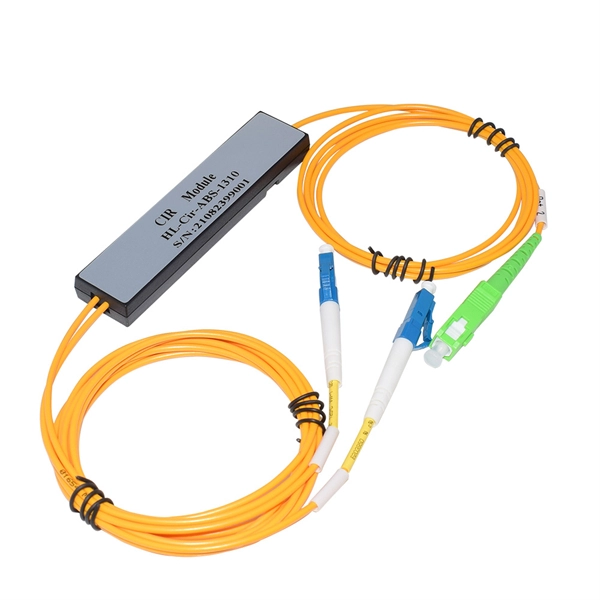
This system enables tracking of the presence and relative intensity of multiple wavelength-division-multiplexed (WDM) data streams that span over a broad frequency band with high resolution, accuracy, and fast measurement update rates. In fiber-optic communications, wavelength-division multiplexing (WDM) is a technology which multiplexes a number of optical carrier signals onto a single optical fiber by using different wavelengths (i., colors) of laser light. This allows multiple channels of data to be transmitted simultaneously. Typically ships in 21 day (s) Actual lead time confirmed upon receipt of order. EDGE HD-DWDM modules incorporate LC APC connections on single fiber ports and MDC APC connections on two-fiber output channel pairs. 6i, 12i and 24i modules are used for the initial channels deployed, while 12u and 24u. Wavelength Division Multiplexing increases fiber capacity by combining (mux) and separating (demux) multiple input channels over a single fiber output. This guide delves into the principles, types, applications, and future trends of WDM. Tailored for professionals sourcing solutions from CommMesh, it. We propose a novel (to our knowledge) and simple real-time optical monitoring (RTOM) system for dynamic spectral analysis of telecommunication signals, involving electro-optic (EO) temporal sampling followed by dispersion-induced frequency-to-time mapping and high-speed photodetection.
[PDF]

The internal configuration of the single-phase distribution box consists of one phase (L), one neutral (N), one earth (PE) wire, and a single-phase busbar system. It also has the main switch and multiple MCBs for branch circuits, as well as for leakage protection with RCD or RCBO. A distribution box, or DB box, is a circuit breaker enclosure. It is a vital part and central hub of any electrical system. The hub distributes electrical power from a single input source to various circuits throughout a building. Whether it's a home, office, or factory, the DB box makes sure power. A distribution box is a key part of electrical systems in buildings. Inside, you'll find parts like circuit breakers and fuses that protect the system from problems like overloads and short circuits. It ensures that electricity flows. A distribution board (DB) is the central component of any power distribution system, providing a safe and organized way to deliver electricity from the main supply to individual circuits. What is a distribution board and why it matters is a fundamental question for engineers and designers of modern. This ultimate guide explains what a distribution box does, its internal components, common types, real-world applications, and how to select the right DB Box for your project. It provides convenience for protection, control and maintenance.
[PDF]

This handbook covers the code of practice in protection circuitry including standard lead and device numbers, mode of connections at terminal strips, colour codes in multicore cables, dos and donts in execution. Also principles of various protective relays and schemes including special protection. Read this document and the documents listed in the additional resources section about installation, configuration, and operation of this equipment before you install, configure, operate, or maintain this product. Users are required to familiarize themselves with installation and wiring instructions. presentation of protection and control relaying. The report will identify methodology behind these practices, present issues raised by the integration of microprocessor relays and the internal logic and external communication configurations, ying. The objective of this presentation is to convey a basic understanding of protective relays to an audience of engineers already familiar with low voltage protective device coordination. HT panel protection relay. The HT power supply is received from GO switch and distributed to the. The handbook for protection engineers includes guidelines on protective circuitry, protective relay principles, and testing procedures for switchgear and relays. It covers standard codes, wiring practices, and norms for protecting generators, transformers, and lines, and provides detailed.
[PDF]