Whether you're building a commercial setup or upgrading an industrial plant, proper cable tray installation ensures neat wiring, safe access, and easy maintenance. But before you lay the first tray or clamp down a single cable, you need a solid plan. This guide breaks. This method statement covers the site installation of the cable tray & ladders and the requirements of checks to be carried out. The Cable Tray system is installed in electrical rooms, plant rooms, and service corridors. This guide breaks down the process step by step. This process is integral to determining the optimal arrangement and configuration of cable trays, which are essential for routing and supporting electrical cables within buildings and. 1. 0 This method statement will serve as a minimum guideline to carry out the Cable Tray Installation activities for commercial buildings, plants and refineries in accordance with Project Drawings and Specifications. This document outlines the key requirements for cable tray layout, installation, and fireproofing in industrial and commercial environments. Route. Below is the detailed cable tray installation method statement not only for cable tray but also applicable for GI ladder and trunking for indoor and outdoor applications and in service rooms like pump rooms, electrical rooms and plant rooms etc. All materials intended for cable tray, ladder and.
[PDF]

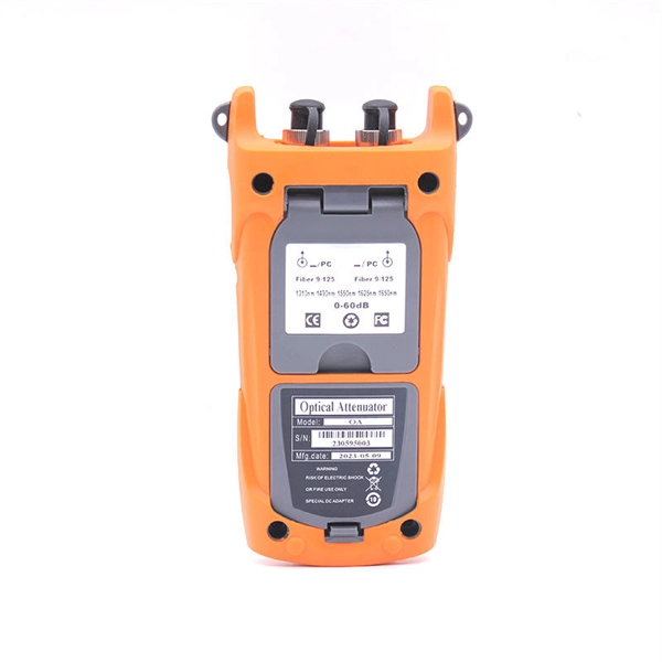
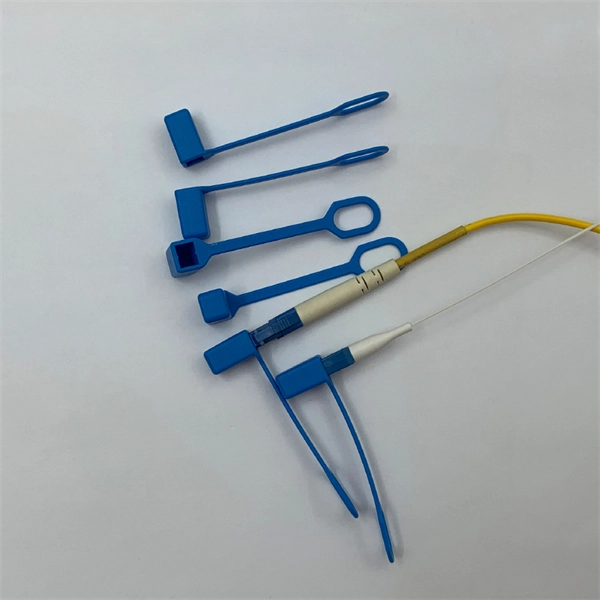
Select the correct wavelength and set your reference. You measure optical power in dBm or insertion loss in dB. Consistent procedures ensure accuracy. Measure total signal loss from fiber, connectors, or splices. Optical fiber attenuation is the attenuation per unit length of optical fiber, and the unit is dB/km. When connecting two optical fibers, there will be loss inside any connector or joint. Consistent measurement techniques. While optical power meters are the primary power measurement instrument, optical loss test sets (OLTSs) and optical time domain reflectometers (OTDRs) also measure power in testing loss. TIA standard test FOTP-95 covers the measurement of optical power. Optical power is based on the heating power. Light Source: The CMA5 Series Light Sources provide an economical and stable laser source for use in point-to-point attenuation measurement. They feature a rugged design, built to withstand the difficult testing environment of fiber optic cable installation and maintenance. The CMA5 Light Sources. When talking about optical measurements, wavelength basically means how far a wave pattern repeats itself, usually measured in nanometers (nm). Commonly, a power meter on its own is used to measure absolute.
[PDF]
In 1880, and his assistant created a very early precursor to fiber-optic communications, the, at Bell's newly established in. Bell considered it his most important invention. The device allowed for the of sound on a beam of light. On June 3, 1880, Bell conducted the world's first wireless transmission between two buildings, some 213 meters apart. Due to its use of an atmospher.
[PDF]

To use a power meter for fiber optic testing, always clean connectors first with lint-free wipes or click-to-clean tools. Select the correct wavelength and set your reference. You measure optical power in dBm or insertion loss in dB. Consistent procedures ensure accuracy. Verify light travels from. The most basic fiber optic measurement is optical power from the end of a fiber. This measurement is the basis for loss measurements as well as the power from a source or presented at a receiver. Typically both transmitters and receivers have receptacles for fiber optic connectors, so measuring the. An optical power meter measures the strength of light traveling through a fiber optic cable, giving you a reading in dBm (decibels relative to one milliwatt). This article will guide you through the methods, instruments, and key considerations for measuring fiber. Fiber optic cabling is the high-performance core of today's datacom networks. As network speeds and bandwidth demands increase, fiber performance requirements have become more stringent. Fiber testing is more important than ever. An OPM uses a photodiode to generate an electrical current proportional to optical power.
[PDF]

Traditional pluggable optical modules are approaching their physical limits in three core dimensions: power consumption control, signal integrity and port bandwidth density. Low Latency: LPO technology eliminates the need for a DSP, reducing a processing step and thus lowering data transmission latency. This advantage is particularly important in high-performance computing (HPC) scenarios, where minimizing latency is a key factor in achieving optimal performance. By. Among the emerging technologies, LPO (Linear Pluggable Optics), NPO (Near-Packaged Optics), and CPO (Co-Packaged Optics) represent three important stages in the evolution of next-generation data center optical networking. Understanding how these architectures differ is essential for designing. Optical communications are emerging as the next AI computing infrastructure frontier, driven by data interconnection bottlenecks. Lumentum's order book is full through 2028, reflecting surging demand for 800G and 1. 6T optical modules, amplified by Nvidia's strategic investment., May 4, 2026 – GlobalFoundries (Nasdaq: GFS) (GF) today announced the introduction of its SCALE™ optical module solution for co-packaged optics (CPO). GF's SCALE. In Feb. 2023, the State Council issued the "Overall Layout Plan for Digital China Construction. ” It proposes six key tasks,including enhancing the efficient.
[PDF]
Electric power distribution systems are designed to serve their customers with reliable and high-quality power. The most common distribution system consists of simple radial circuits (feeders) that can be ove.
[PDF]
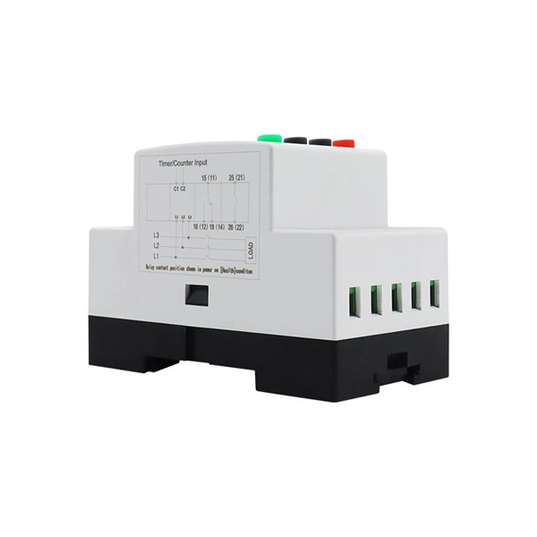
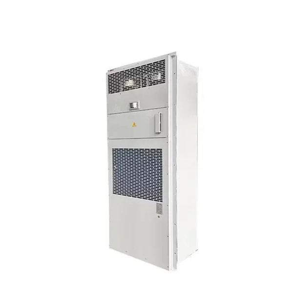
The distribution box is divided into power distribution box and lighting distribution box, which is the final equipment of the power distribution system. Both are strong electricity. The distribution box is a low-voltage power distribution device that assembles switchgear. A panelboard is a component of an electrical distribution system which divides an electrical power feed into branch circuits, while providing a protective circuit breaker or fuse for each circuit, in a common enclosure. A panelboard services to protect branch circuits from overloads and short. The distribution box is an electrical equipment with the characteristics of small size, easy installation, special technical performance, fixed position, unique configuration function, no site restrictions, widespread application, stable and reliable operation, high space utilization rate, small. A distribution box is according to the electrical wiring requirements of the switchgear, measuring instruments, protection appliances, and auxiliary equipment assembled in the enclosed or semi-enclosed metal cabinet or screen width, constituting a low-voltage power distribution device.
[PDF]

While optical power meters are the primary power measurement instrument, optical loss test sets (OLTSs) and optical time domain reflectometers (OTDRs) also measure power in testing loss. TIA standard test FOTP-95 covers the measurement of optical power. This measurement is the basis for loss measurements as well as the power from a source or presented at a receiver. Typically both transmitters and receivers have receptacles for fiber optic connectors, so measuring the. You need a power meter to measure power in a fiber optic system; most power meters come with a screw-on-adapter that matches the connector being tested and a little aid from the network electronics to turn on the transmitter. During the measurement of power, the meter must be set to the proper. Fluke Networks sets the standard in network testing with its advanced range of fiber optic power meters and fault locators, designed to ensure the highest precision in fiber optic meter readings and power evaluations. This is measured in decibels (dB). Splitters, fusion splices, connectors and. To use a power meter for fiber optic testing, always clean connectors first with lint-free wipes or click-to-clean tools. Select the correct wavelength and set your reference. Consistent procedures ensure accuracy.
[PDF]
At Multilink, we offer traffic power solutions to keep traffic signals, camera equipment, illuminated street signs and other tech up and running. Power traffic signals, camera equipment, lighting and other t.
[PDF]
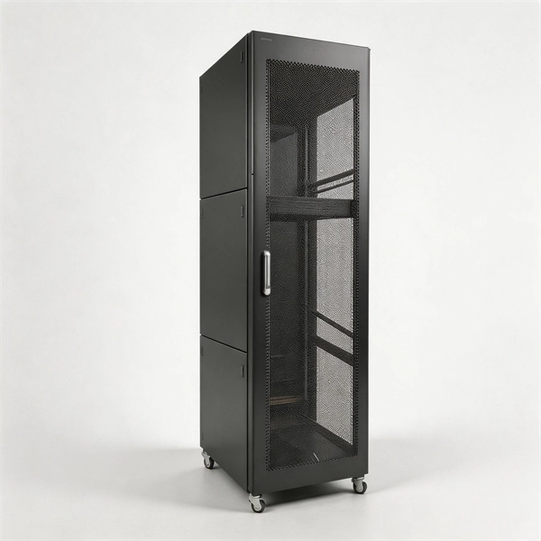
Quality Libya power strips, in stock, for standard duty applications up to industrial applications. Versions designed for PDU power distribution purposes in data centers and server room applications. As Data Centers evolve to handle increasing power densities driven by AI, cloud computing, and high-performance applications, PDUs have advanced from simple power strips to intelligent systems offe ing Monitoring, Remote Management, and. Voltz engineers high-performance power distribution solutions for mission-critical infrastructure. Integrated protection. UL-891 and ISO 9001:2015 compliant. The space-saving PDU is easy to move and adapt to the future demands of the data center. The PDU offers superior power protection and monitoring, and the flexibility. From basic PDUs, to monitored and switched rack power distribution units, to locking receptacles, Vertiv's solutions will offer the power distribution you need, as well as remote monitoring and management of your assets' power usage, so you can rest assured everything is running at peak. Hyper Power Distribution Units (PDUs) are engineered to redefine efficiency, flexibility, and reliability in mission-critical environments. Designed for the most demanding applications, our PDUs support transformer capacities ranging from 300 kVA to 2,000 kVA, providing scalable solutions for.
[PDF]
A site power distribution board is usually an electrical distribution box equipped with various sockets to provide power for different equipment and machinery. A construction power distribution box may also have earth leakage circuit breakers to ensure safety on the construction site. Temporary construction power system s are essential for delivering safe and reliable electricity across dynamic job sites. From powering heavy machinery to supporting lighting and tools, temporary power boxes must operate in harsh outdoor conditions while ensuring electrical safety and flexibility. That's where a construction site distribution board comes into play. However, distributing power correctly on a construction site can be challenging, especially considering that different types of equipment and machinery have different power requirements. A. Temporary power distribution boxes provide a safer way to manage power while keeping your workspace tidy. They handle everything from simple 120/240V single-phase loads to powerful. Power Temp Systems' power distribution equipment with robust portable options provide seamless solutions to keep job site equipment humming. Power outages a problem? Count on Power Temp Systems solutions, tailored to your needs, to keep your project on schedule and ensure your team has all the. Temporary power distribution boxes are a budget-friendly way to supply electricity to a remote area. You can use them to power electrical equipment, lighting systems and more.
[PDF]
Electric power distribution systems are designed to serve their customers with reliable and high-quality power. The most common distribution system consists of simple radial circuits (feeders) that can be ove.
[PDF]
Temporary power distribution boxes boost efficiency and safety by allowing workers to finish jobs more quickly. They're also durable, making them suitable for frequent transportation and harsh environments.
[PDF]
Versions designed for PDU power distribution purposes in data centers and server room applications. In this Suriname project, the client needed exactly that kind of logic: a power-distribution structure that separated critical loads, supported safe protection, and made long-term plant management easier rather than more complicated. The Suriname bottling plant required a centralized low-voltage. The Republic of Suriname has received financing in the amount of USD 105,695,000. 00 (One Hundred Five Million and Six Hundred Ninety Five Thousand United States Dollar) from the Islamic Development Bank (IsDB) Group and the Saudi Fund for Development (SFD) toward the cost of the Expansion of. right Castalia Limit d. Castalia is not liable for any loss caused by re ance on this document. Multiple outlet power strips are manufactured in accordance to Suriname standards with agency approvals. Quality Suriname power strips, in stock, for standard duty applications up. Can't find the product you need? Please give us feedback Dongfeng-covering various types of distribution boxes_rich and diverse product system, covering various types of distribution boxes and cabinet products. the Procurement Guidelines. In addition, please refer to paragraphs 1. 5 setting forth IsDB's pol o at fundable fee of USD 500. The method of payment will be direct deposit to a specified account number which will be shared after we have recei ed the written application.
[PDF]

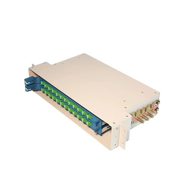
Communication networks are an integral part of interconnected transmission lines in a power grid, analogous to the spinal cord for control signal and information exchange among substations, data hubs, and load dispatch centers. This article cov. Communication networks are an integral part of interconnected transmission lines in a power grid, analogous to the spinal cord for control signal and information exchange among substations, data hubs, and load dispatch centers. This article covers the major trend and design aspects of fiber optics communication link in power transmission line netwo. The communication network in the power grid is one of the most interrelated systems that require perfect compliance in equipment and protocol selection. While the high voltage components are relatively unchanged over decades in terms of operating principles, the communication protocols and equipment are seeing astonishing advancements every year. S. 2.1 Knowhow of prevailing setupWhile the primary objective is always to get the best solution for the lowest price, in the case of extension projects, the design engineers must also keep an eye on the existing setup. The issue of back-compatibility and upgradationsshould be properly accessed in existing equipment, even more so in the case of proprietary legacy setups. Figure below illustrates one such group of communication equipment in existing substations that might need proper interfacing and compatibility adapters befo.
[PDF]