The main group of impedance relays is distance protection devices. loss of synchronism protection, loss of excitation protection, or impedance automatics like fault locator. Impedance Relay Definition: An impedance relay, also known as a distance relay, is defined as a device that triggers based on the electrical impedance measured from a fault's location to the relay. Working Principle: The operation of an impedance relay hinges on the balance of voltage-induced. When a system has too many radial lines protection using time delay overcurrent relay becomes impractical. This problem can be solved to an extent by using distance relays. Distance relays uses voltage and current to calculate the. Distance relay protection has been defined as a part of relay protection in power systems that detects and isolates faults based on the distance between the relay and fault points. Unlike overcurrent relays, which only respond to the magnitude of current, a distance relay measures the impedance of. Such relays are called Distance Relays or Impedance Relays. In an impedance relay, the torque produced by a current element is opposed by the torque produced by a voltage element. The relay will operate when the ratio V/I is less than a predetermined value. The voltage transformer measures the voltage across the protected equipment, while the current transformer measures the current flowing through it.
[PDF]
Includes dual power supplies, hot-swappable modules, link aggregation (LAG), and support for HSRP/VRRP. Modular chassis or stackable designs make it easy to scale as your network grows. 1X support, SNMP, CLI/Web GUI, and network access control. There are different types of enterprise switches that perform various roles in these layer-based or hierarchical ethernet networks. This white paper introduces the following three types of network switches and further discusses the selection criteria for each switch. What is a network switch? So, what is a network switch? A network switch is a vital component of a computer network that. What is Spanning Tree Protocol (STP) and why is it important in core switch networks? Can I use a cloud-managed core switch? How does Quality of Service (QoS) impact core switch performance? What Is a Core Switch in Networking? Understanding the Backbone of Your Network A core switch in networking. Providing The Most Competitive Networking Products For Global Customers! In the realm of system networking, three key types of switches are frequently mentioned: access switches, aggregation switches, and core switches. The part of the network that directly connects to user devices is referred to. What Is a Core Switch? The Definitive Guide to Network Architecture A core switch is a high-capacity, high-performance Layer 3 switch positioned at the physical backbone of an enterprise network. This post mainly explores the confusing problem: core.
[PDF]
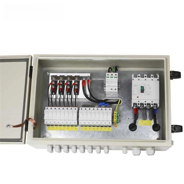
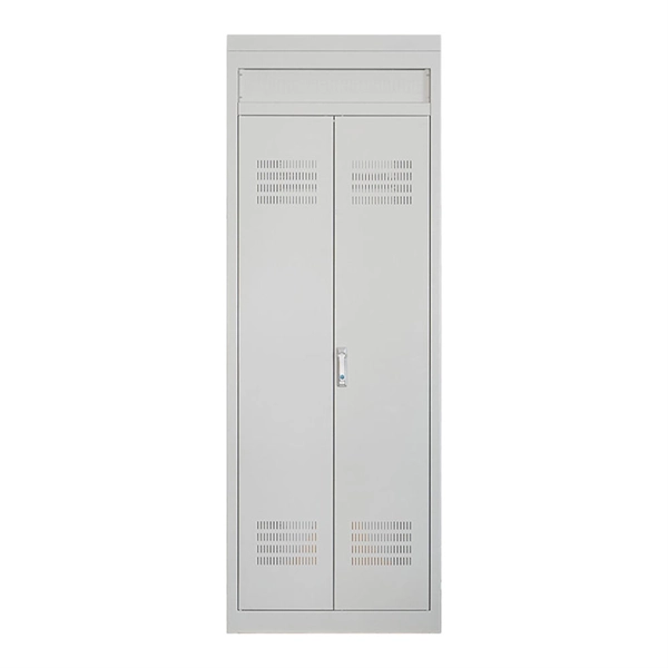
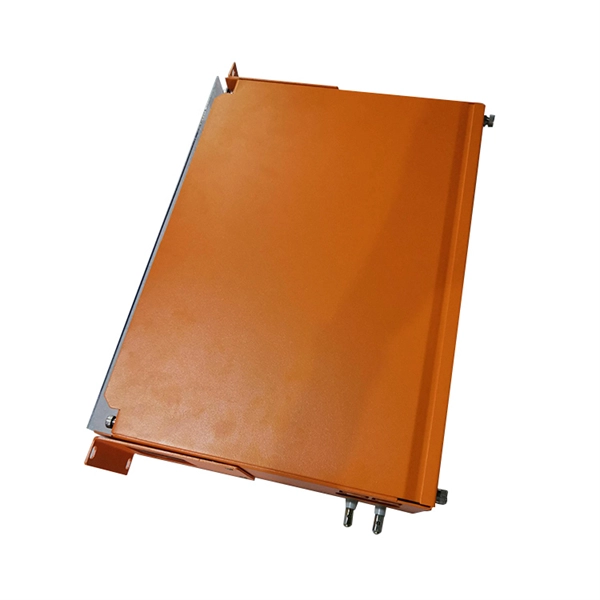
The BXM, BXD, and BXJ explosion-proof distribution boxes are engineered for the safe operation and control of specialized equipment in hazardous environments. Durable Hexlon Explosion Proof Distribution Boxes and Electrical Enclosures, IECEx and ATEX certified for Zone 1 and Zone 2. Order Explosion Proof Illumination Distribution Boxes from Warom Technology, a trusted manufacturer and supplier, designed for industrial lighting automation, hazardous electrical systems, nuclear illumination, defense applications, and waterproof, dustproof environments. ◆ The explosion-proof. It is widely used in flammable and explosive gas environment such as oil exploitation, refining, chemical industry, offshore oil platform, oil tanker, etc. Ideal for marine platforms, chemical tankers, LNG vessels, and dangerous cargo wharfs, these robust distribution boxes ensure reliable. Explosion Proof Box, SUREALL Low-voltage Control Guide Driving the state of the art innovation for power distribution and control for electrical equipment in harsh and hazardous location Explosion proof box, also called explosion proof boxes, include but not limit to explosion proof electrical. We supply certified explosion proof distribution box & Atex Transformer -Appleton, ATKON, CZ, CEAG, brands for safe and reliable industrial use.
[PDF]

The WannaCry ransomware attack was a worldwide cyberattack in May 2017 by the WannaCry ransomware cryptoworm, which targeted computers running the Microsoft Windows operating system by encrypting data and demanding ransom payments in the form of bitcoin cryptocurrency. It was propagated using EternalBlue, an exploit developed by the United States National Security Agen. DescriptionWannaCry is a , which targets computers running the by encrypting (locking) data and demanding ransom payments in the. The attack began on Friday, 12 May 2017, with evidence pointing to an initial infection in Asia at 07:44 UTC. The initial infection was likely through an exposed SMB port, rather than as initially ass. Linguistic analysis of the ransom notes suggested the authors were likely fluent in Chinese and proficient in English, as the versions of the notes in those languages appeared to be human-written while the rest seeme. The ransomware campaign was unprecedented in scale according to, which estimates that around 200,000 computers were infected across 150 countries. According to, the four mo.
[PDF]
This guide covers everything: what fiber optic pigtails are, how they differ from patch cords, which connector and polish type to specify, how to choose between mechanical and fusion splicing, and the real-world applications where pigtails are the right call. Types and Applications A pigtail connector is a short cable with a connector on one end and bare (stripped) wire or fiber on the other. In fiber optics, pigtails are fusion-spliced to field fiber inside splice trays — the most common termination method in telecom and data center networks. In. Whether it's an electrical system in your car, home, or factory, the quality of the connection is essential, and that's where pigtail connectors come in. These small, often overlooked components ensure a strong, safe electrical connection. It serves as a bridge, allowing technicians to repair specific connection points without disturbing the rest of the system. By the end, you will have a comprehensive understanding of why pigtails deserve a place in every fiber deployment toolkit. People often make this connection in the field, where they must make temporary repairs or. Executive Summary: A fiber optic pigtail is one of the most commonly specified yet least understood components in structured cabling. Get the wrong connector type, the wrong polish, or skip proper fusion splicing technique—and you're looking at elevated signal loss, increased back reflection, and a.
[PDF]
The Tuvalu Vaka Cable system contains four fiber pairs that land in Funafuti, the capital of Tuvalu. Tuvalu's first undersea telecommunications cable — the Vaka Cable — is now live, marking a major milestone in the country's digital transformation. The cable will deliver more reliable and affordable internet across Tuvalu, improving digital access and inclusion. The USD 56 million (AUD 80 million). The Tuvalu Vaka Cable is the first international telecommunications cable connecting Tuvalu, being a branch of 688km linking Funafuti, the capital of Tuvalu, with the trunk of the Bulikula cable system, part of Google's Pacific Connect initiative. The new undersea cable will deliver faster. TUVALU celebrated the official activation of its submarine cable, the Tuvalu Vaka Cable, on 24 October 2025. Funded by Australia, the United States, Taiwan, New Zealand and Japan and supported by Google's inclusion of Tuvalu in the Central Pacific Connect system, the activation of the cable is a. Tuvalu Telecommunications Corporation (TTC) announced the successful landing of the nation's first submarine cable, the Tuvalu VAKA Cable, marking a monumental leap forward for connectivity and digital inclusion for Tuvalu.
[PDF]
A spectrometer is a scientific instrument used to separate and measure components of a physical phenomenon. Spectrometer is a broad term often used to describe instruments that measure a continuous variable of a phenomenon where the spectral components are somehow mixed. In a spectrometer can separate white and measure individual narrow bands of color, called a spectrum. A.
[PDF]
Fiber optic couplers can either be passive or active devices. Passivefiber optic couplers are said to be passive as no power is required for operation. They are simple fiber optic components that are used to re.
[PDF]
If unavoidable, the distance should be no less than 500 mm, and a corrosion-resistant partition should be used. Failure to maintain sufficient spacing can result in several critical issues that could affect the safety and functionality of the installation. Let's explore why this. AFTER FIREPROOFING AND INSULATION IS INSTALLED 4. NOMINAL MINIMUM SEPARATION BETWEEN CONDUITS OF REDUNDANT ELASS IE DIVISIONS IS C INCHES LE MANI ERRATE REDUCED TO | INCH FOR CONDUITS ROUTED THROUGH WALL AND FLOOR PENETRATIONS, AND ON CONCLIIT RUNS WHERE THE SEISMIC ATTACHMENT CRITERIA, AS SHOWN. en completely installed, without damage either to conductors or structural system use maintain spacing or to keep cables in place when the tray is ect the minimum bend ra-dius for cables as they exit the bottom of the cable tray. The NEC requires that cable trays must be supported by members at an interval specified by the cable tray manufacturer, but not more than 5 feet for horizontal runs to support the weight of the cables and other loads. The NEC has a requirement for ladder-type cable trays. The rungs cannot be more. IEEE Guide for the Design and Installation of Cable Systems in Substations IEEE Std 525™-2007 (Revision of IEEE Std 525-1992/Incorporates IEEE Std 525-2007/Cor1:2008) IEEE Guide for the Design and Installation of Cable Systems in Substations Sponsor Substations Committee of the IEEE Power.
[PDF]
Fiber optic transmission distance varies based on fiber type, environmental conditions, and equipment selection. This guide explores the key factors affecting fiber optic transmission distance and provides practical selection guidelines for a stable and cost-effective network. Receiver Sensitivity Higher receiver sensitivity means that it can detect weaker optical signals. Even if the optical signal power is low, the receiver can still detect and decode the signal correctly, extending the transmission distance of fiber optic communication. Another consideration is that. Fiber optic cable transmission distance is determined by two primary physical factors that affect signal quality as light travels through the fiber medium. For most enterprise or data center applications using multimode fiber, the practical limit sits between 300 m and 550 m. Single-mode. Estimate one-way and round-trip timing for fiber runs, optics, and active hops in home labs and backbone links. Direct point-to-point links with OS2 single-mode 1310 nm typically use 10 km+ of practical reach. Configuration type Fiber profile Route length Measured in feet for imperial mode. Apply a waste factor based on site practice. Click Calculate to see totals and the breakdown. Use the export buttons to share results. For critical links, verify on drawings and allow extra for rework. Fiber length takeoff starts with a measured route. Break the pathway into segments for tray runs.
[PDF]

Fiber optic cable can be run anywhere from 300 meters up to 80 kilometers (roughly 50 miles) depending on the cable type, transceiver used, and network standard. For most enterprise or data center applications using multimode fiber, the practical limit sits between 300 m and 550 m. Fiber optic cable transmission distance is determined by two primary physical factors that affect signal quality as light travels through the fiber medium. The greater the distance, the greater. Many factors decide the fiber cable distance, but the key factors include the below six aspects. Attenuation First is the attenuation of the optical fiber. OM2 extends this to 82 meters. OM1 fiber and OM2 fiber don't support these higher speeds. OM5 fiber matches OM4 at. For instance, without amplifiers, single-mode fiber can reach 50-60 miles and can support data rates of 1 Gbps or 10 Gbps. With amplifiers, such as Erbium-doped fiber amplifiers (EDFAs), the distance can be extended to 600 miles or more, and even further with additional amplifiers for long-haul.
[PDF]

Recommendation ITU-T G. 654 describes the geometrical, mechanical and transmission attributes of a single-mode optical fibre and cable which has the zero-dispersion wavelength around 1300 nm wavelength, and which is loss-minimized and cut-off wavelength shifted at around the 1550 nm. Recommendation ITU-T G. 649 Optical fibre cables G. 659 Characteristics of optical components and subsystems Characteristics of optical systems G. E fibre: empowering ultra high-capacity long-haul transmission. Sumitomo Electric. TRANSPORT A S ACCESS NE around the 1550 nm wavelength region. This is the latest revision of this Recommen. ata rates at and above 800 Gb/s over distances further than a few hundred kilometres. Over longer distances, such as between two data centres, signal regeneration or addition ng-distance transmission,” said Xavier Renard, Telecom Marketing Di ector at ACOME. “It's also c ucial that we consider the. ACOME Group and Sumitomo Electric Industries, Ltd. have announced a new proposal for long-haul optical network cables that will 'break through the glass ceiling' of data transmission limits to ensure the ever-growing demands of data centres can be supplied. To support these high capacity systems in terrestrial backbone networks, low attenuation and large core area fibers compliant with Recommendation ITU-T G 654. E were introduced and have been extensively deployed worldwide.
[PDF]

Its typical transmission distance is 20km or 40km. For instance, some ethernet switch manufacturers refer to the 1000BASE-LH SFP as the 1G 1310nm 40km SFP transceiver, which indicates the module's transmission distance and wavelength. The 10G SFP+ dual-fiber optical module is a small pluggable optical transceiver that adopts a dual-fiber bidirectional design. It completes signal transmission (Tx) and reception (Rx) through two independent optical fibers, ensuring the stability and reliability of signal transmission. An SFP (Small Form-factor Pluggable) module transmits data over fiber using specific wavelengths and power levels, which directly influence how far the signal can travel before degradation occurs. This is why two. If the optical module works at a wavelength near 850nm (880nm) or 910nm (940nm), then the module is a multi-mode fiber (MMF) optical transceiver, and if the working wavelength is 1310nm or 1550nm, it is a single-mode fiber (SMF)optical module. Generally, the maximum transmission distance(generally. The transmission distance of optical transceiver modules is divided into short distance, medium distance, and long distance. A 1-core module uses a single fiber core for data transmission, while a 2-core module uses two cores. o Think of a highway. Chromatic dispersion This is a key factor affecting single mode fiber distance.
[PDF]

A: Single mode fiber can typically transmit up to 160 km, and with dispersion compensation, it can exceed 200 km. Q: How far can multimode fiber go? A: The transmission distance of multimode fiber depends on the fiber type and data rate. However, for long-distance applications (e., metro and backbone networks), single mode fiber provides lower attenuation and future-proof scalability, resulting in lower long-term operational costs. For example, a fiber optic cable with a distance of 1km supports a bandwidth of 500MHz, while a fiber optic cable with a distance of 2km can only support a bandwidth of 250MHz. There are three main reasons for this: First, high-bandwidth. In the complex landscape of fiber optic infrastructure, selecting the right cable type—single-mode (OS1/OS2) or multimode (OM1/OM2/OM3/OM4/OM5)—can define a network's speed, reach, and cost-effectiveness. This guide dissects their technical nuances, evolution, and real-world applications. Fiber optic cable transmission distance is determined by two primary physical factors that affect signal quality as light travels through the fiber medium. Minimum Distance for Single-Mode Fiber: No Specific Limitation. Single-mode fiber is widely used in. Single-mode fiber (SMF): Uses a single light path, enabling it to transmit data over longer distances with less signal loss.
[PDF]