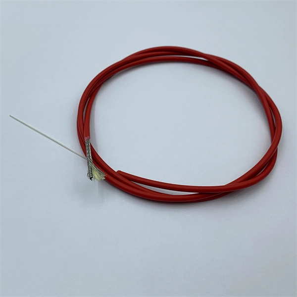
Precast concrete trench systems provide protection and easy access to power, communication, fiber optic, control, and signal wires and cables. Engineered precast trench is used in the power, utility, and transportation industries and can also be used in conjunction with catch basins, inlets, and. Completing Outside Cable Plant Installation. Underground cables are pulled in conduit that is buried underground, usually 1-1. 2 meters (3-4 feet) deep to reduce the likelihood of accidentally being dug up. In extreme cold climates, cables may need to be buried at greater depths where there. THE SOLID APPROACH TO TRENCHING. Made of a unique, patented. Trenwa is the original manufacturer of precast concrete trench and offers the broadest line of proven trench systems. Trusted by Industry Leaders: Trenwa has been a go-to partner for North American infrastructure projects for over for over 60 years. Request a quote today to see how our products can. Waskey's Precast Cable Trench System offers a durable, customizable solution for protecting and organizing critical infrastructure. If you need any help, be sure to reach out. Precast Concrete Trench for underground utility purposes. Primarily used for enclosure of electrical, communication, power cables, and piping.
[PDF]

Numerical relay are embedded with specialized digital signal processor (DSP) as the computational hardware. By using DSP as the relay's processor, the relay is capable of meeting the fundamental protective requirements such as reliability, sensitivity, selectivity and speed . Thus, various protective devices are used to protect the power system, of which digital signal processor (DSP) numerical relays are capable of significantly improve protection operations. Therefore. Manuals and User Guides for Samwha DSP DSP-VIP-PM Motor Protection. We have 1 Samwha DSP DSP-VIP-PM Motor Protection manual available for free PDF download: Manual Samwha dsp DSP-VIP-PM Motor Protection Pdf User Manuals. View online or download Samwha dsp DSP-VIP-PM Motor Protection Manual. Many of the new protection relays are microprocessor based and are generally referred to as numerical relays. This means that signals from transducers are sampled at fixed time intervals, digitally encoded, and processed by equipment which resembles a computer to derive relaying information, e.
[PDF]
The development of the relay protection based on open architecture is a relevant direction of electrical and electronic engineering. The paper presents the problem of the modern microprocessor-based relay prote.
[PDF]

The main group of impedance relays is distance protection devices. loss of synchronism protection, loss of excitation protection, or impedance automatics like fault locator. Impedance Relay Definition: An impedance relay, also known as a distance relay, is defined as a device that triggers based on the electrical impedance measured from a fault's location to the relay. Working Principle: The operation of an impedance relay hinges on the balance of voltage-induced. When a system has too many radial lines protection using time delay overcurrent relay becomes impractical. This problem can be solved to an extent by using distance relays. Distance relays uses voltage and current to calculate the. Distance relay protection has been defined as a part of relay protection in power systems that detects and isolates faults based on the distance between the relay and fault points. Unlike overcurrent relays, which only respond to the magnitude of current, a distance relay measures the impedance of. Such relays are called Distance Relays or Impedance Relays. In an impedance relay, the torque produced by a current element is opposed by the torque produced by a voltage element. The relay will operate when the ratio V/I is less than a predetermined value. The voltage transformer measures the voltage across the protected equipment, while the current transformer measures the current flowing through it.
[PDF]
This paper analyzes the basic principle and function of relay protection, summarizes the common fault types, and analyzes the fault analysis methods and treatment measures combined with actual cases. A method of fault tracking for relay protection devices is presented in this paper. Fault tracking means that after the failure of relay protection devices, the anomalies and warning informa-tion are obtained through data-mining technology, and then, the fault tracking algorithm is used. Relay fault diagnosis refers to the process of identifying and analyzing faults or abnormalities in protective relays. However, in actual operation, the relay protection device may cause failure due to hardware failure, software problems or external. For a long time, the fault diagnosis technology of relay protection consists of isolated cases and does not have a systematic method.
[PDF]
This article will focus on the failure rates of optical modules, analyze the primary causes of failure in traditional Digital Signal Processing (DSP) modules, compare failure rates utilizing LPO technology, and discuss the advantages presented by LPO modules. Linear Pluggable Optics (LPO) are a new optical transceiver technology. The idea is simple: instead of a DSP (digital signal processor) inside the module – replacing it with transimpedance amplifier (TIA) and a driver chip with high linearity and EQ capability – LPO shifts signal processing into. Copyright 2023, Coherent. Next-generation 400G and 800G modules for data centers, AI clusters, and telecoms — validated in a European lab, ready to ship from Europe. What is Low-Power Optical Transceivers (LPO)? Linear Pluggable Optics (LPO) replace the DSP inside the optical module with linear analog components, shifting. QSFP-DD LPO TRANSCEIVER DESIGNED FOR PCIE® GEN 5. 0 over optical link, enabling scalable server disaggregation and efficient rack-to-rack interconnects ideal for AI/ML and. Led by Cisco Optics experts, this MSA quickly gained broad industry support due to its vision to create cost-effective solutions for high-density multi-terabit switching, routing, and transport networks. The goal was to define optical specifications that allow for future 100G and 400G pluggable.
[PDF]

Support Portal provides access to various services for Nokia Customers and Partners, such as Product Documentation, SW Downloads, Ticket Creation and Case Handling. The latest generation of Digital Coherent Optics (DCO) pluggable transceivers represents a breakthrough in the optical networking industry. By combining advances in silicon photonics and Digital Signal Processors (DSP) with Quad Small Form-factor Pluggable – Double Density (QSFP-DD) form factor. Ciena's WaveLogic 6 Extreme 1. 6T quantum-safe encryption solution on the Waveserver platform was designed with this in mind, supporting QKD system interworking and NIST-certified PQC algorithms. It delivers an always-on, wire-speed encryption solution, without impacting performance or adding. 400 Gigabit Ethernet (400G) transceivers are optical modules capable of handling data rates of 400 Gbps. With a transmission rate of up to 400 Gbps, 400G transceivers offer double the capacity of their predecessor (200G transceivers). 400G. ONU, or Optical Network Unit, is a networking device that connects your home or business to the internet using fiber optic cables. It's like a bridge between the vast internet world and your personal network. ONU is a small device that sits somewhere in your house. When you connect your computer. C-Data's ONU products include models that offer data, data + voice, data + CATV, and Triple Play services. They support TR-069 and provide excellent compatibility with third-party OLT systems.
[PDF]
This involves achieving thermal resistance values of less than 1°C/W for high-power optical components and ensuring temperature uniformity across the package to prevent thermal gradients that could degrade system performance. Being an industry group uniting representatives of the data and optical worlds, OIF's purpose is to accelerate the deployment of interoperable, cost-effective and robust optical internetworks and their associated technologies. Optical internetworks are data networks composed of routers and data. Co-packaged optics (CPO) has emerged as an ultimate solution for achieving the ultra-high bandwidths, shoreline densities, and energy efficiencies required by future GPUs and network switches for AI. Microring modulators (MRMs) are well-suited for transmitters due to their compact size, high energy. Source: IEEE 802. 3 Beyond 400G Study Group. CPO is widely regarded as a promising. The rapid surge in global data traffic, driven by artificial intelligence and hyperscale data centers, has established copackaged optics (CPO) as a pivotal technology for next-generation high-bandwidth and low-power interconnects. Introduction The CPO JDF plans to release three documents focused on different elements of Co-Packaged Optics (CPO): the.
[PDF]
These switches are vital for Chile's mining and solar industries due to their small size and high reliability in extreme conditions. This guide will help you understand why these compact solutions are the new standard for the Chilean power grid in 2026. Compact load break switches in Chile are specialized electrical devices used to safely disconnect power under load. They must comply with SEC standards and IEC 60947. What Is a Compact Load Break Switch? A compact load break switch. E-Energy specializes in developing projects and solutions in SCADA, control, communications, and electrical protections for generation plants and substations. Their scope includes electrical and mechanical maintenance of various assets, such as switchgear and protection systems, ensuring compliance.
[PDF]

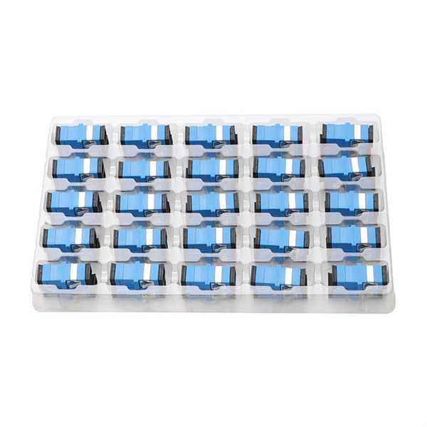
Protect fiber optic cable connections:The joint box provides physical protection for the fiber optic cable connection parts to prevent damage to the fiber optic cable caused by external environmental factors such as moisture, dust, chemical corrosion and mechanical damage. Provide a stable. Fiber optic sleeves are protective devices used for fiber optic connections. Splice protection sleeve, usually made of plastic or metal, are used to secure and protect the fusion joint between two optical fibers. Fiber Cable Joint Box is attributed to the mechanical pressure sealing joint system. Fiber Cable Joint Box is a continuous protection device for supplying optical, sealing and mechanical strength continuity between adjacent optical. The optical fiber terminal box is the terminal joint of an optical cable, one end of which is an optical cable, and the other end is a pigtail, which is equivalent to a device that splits an optical cable into a single optical fiber. The user optical cable terminal box installed on the wall, its. Fiber Optic Splice Closure is designed to protect optical fibers from debris, dirt, dust, moisture and water. As much of the fiber system is outside in a harsh environment, these fiber optic splice closures are designed to meet the tough protection requirements of fiber-optic splices. UnitekFiber. Overview Application of Optical Fiber Splice Closure/Joint Box/Joint Closure: 1. CATV environment.
[PDF]

Generator protection relays are devices that detect abnormal operating conditions and isolate the generator from the system to prevent damage. These relays act as the first line of defense and are installed with strict adherence to IEC Standard for Protection Relays. Protecting generators from different electrical, mechanical, and thermal stresses is known as generator protection. To safeguard machines from overloads and unusual circumstances, preventive measures are required. Faults are inevitable even with effective design, construction, and operation. Below is an overview of the different types of relays used in generator systems, their functions, and their specific applications. Electromagnetic relays use. Generator Protections are broadly classified into three types: Class A, B and C. Class A covers all electrical protections for faults within the generating unit in which generator field breaker, generator breaker and turbine should be tripped. What Are Generator Protection Relays? Generator protection. There are various protection relays and those are used for protection against a wide variety of conditions. The fundamental principles that are covered in this course are equally applicable to. IEEE C37. 2 defines the IEEE “numerical” function designation for all protective relay functions. This presentation primarily uses the designations from the Beckwith M-3425A relay, which in most cases follows IEEE C37.
[PDF]

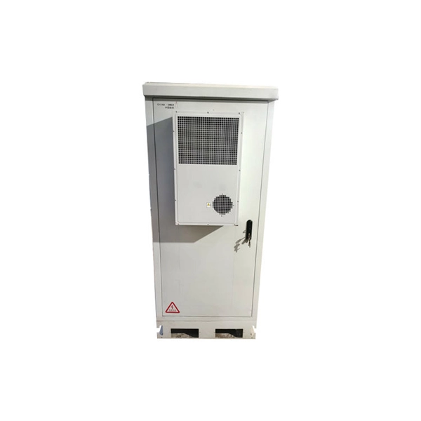
The International Protection (IP) rating system defines minimum requirements for water and dust ingress protection, with outdoor applications typically requiring IP65 or higher ratings. Weatherproof outdoor distribution boxes ensure reliable power distribution in challenging environments by protecting against moisture, dust, and temperature extremes. Key design points include high-quality materials like ABS plastic, aluminum, and stainless steel that resist corrosion and UV. (1) Waterproof distribution box engineered for harsh outdoor and industrial environments, providing IP65–IP68 sealing against dust, rain, and UV. Beyond preventing acute water damage, these enclosures also protect against humidity-related. Yet one factor often overlooked is how well electrical components are protected from dust and moisture. That's where Ingress Protection (IP) ratings come in. If you've ever bought a weatherproof junction box or a distribution enclosure, you've probably noticed codes like IP65, IP67, or IP68 printed. Low voltage distribution box outdoor use requires IP65 or NEMA 4X ratings, corrosion-resistant materials, and proper sealing for lasting weather protection. You use a low voltage distribution box to keep electrical systems safe outside. Let's take a closer look at NEMA ratings and other weatherproofing considerations for.
[PDF]

This article describes the anti-pumping relay, its definition, function, and circuit diagram. In a circuit breaker it is desired that when close and trip operation is performed on the circuit breaker with the closing coil energized, the subsequent closing operation should be prevented. So let's. Anti-Pumping relay is nothing but a NO contact, which means when the circuit breaker in closed condition the relay will be as NO point and if the circuit breaker in open condition the relay will be as NC Condition. The anti-pumping relays is connected in series with the circuit. An anti pumping relay (also called antipumping relay or Y-relay and ANSI 94 Trip or Trip-Free Relay) is a protective device that prevents a circuit breaker from closing repeatedly when a continuous close command is present. In simple terms, it stops your circuit breaker from “pumping” – which means. Anti-pumping relays are used in circuit breakers to prevent the breaker from closing unexpectedly after tripping. If the TNC switch fails (Trip normal close) or there is any problem with the CB (circuit breakers) closing circuit, the continuous CB (circuit breakers) close command can be extended to. Why is the Anti-Pumping Relay Used? A circuit breaker is a very important equipment for a high-voltage power system. It protects the system from high current or voltage during a faulty condition.
[PDF]
Thermal relays are the perfect solution for providing protection to motors which provides the most precise tripping for the electric motor during single phasing and overload. This article discusses an overview.
[PDF]
The original unstructured record data for the defect of the relay protection devices (RPDs) may contain problems influencing the data mining, and it is lack of quantitative evaluation. So the purpose of this.
[PDF]