The primary application of fiber Bragg gratings is in optical communications systems. They are specifically used as. They are also used in optical and with an, or (OADM). Figure 5 shows 4 channels, depicted as 4 colours, impinging onto a FBG via an optical circulator. The FBG is set to reflect one of the channels, here channel 4. The signal is reflected back to the circulator where it is directed down and dropped ou.
[PDF]
The first in-fiber Bragg grating was demonstrated by in 1978. Initially, the gratings were fabricated using a visible laser propagating along the fiber core. In 1989, Gerald Meltz and colleagues demonstrated the much more flexible transverse holographic inscription technique where the laser illumination came from the side of the fiber. This technique uses the interference pattern of ultraviolet laser light to create the periodic structure of the fiber Bragg grating.
[PDF]
A compact fiber Bragg grating (FBG)-based strain sensor has been developed by embedding an FBG inside a 3D-printed structure, allowing the comparison of FBG responses across different filaments such a.
[PDF]
For high intracavity powers (e. tens of watts), however, detrimental thermal effects can occur, such as a shift of the reflection band and a decrease of reflectance. For not too high power levels, volume Bragg gratings can also be used in spectral beam combining. There are fiber Bragg gratings. An optical fiber grating is a small segment within an optical fiber altered to act as a selective filter for light. This treated area functions like a specialized mirror, reflecting a specific wavelength of light while allowing all other wavelengths to pass through. This microscopic structure. Optical fiber grating technology serves as a foundational stone in modern communication and sensing systems. This technology relies on periodic structures within optical fibers that modify the propagation of light, enabling a myriad of applications ranging from telecommunications to environmental. Fiber Bragg grating (FBG) sensors have emerged as advanced tools for monitoring a wide range of physical parameters in various fields, including structural health, aerospace, biochemical, and environmental applications. This review provides a comprehensive overview of FBG sensor technology. A fiber Bragg grating (FBG) is a type of distributed Bragg reflector constructed in a short segment of optical fiber that reflects particular wavelengths of light and transmits all others. This can be achieved by making use of fiber photosensitivity. At each interface between two regions.
[PDF]
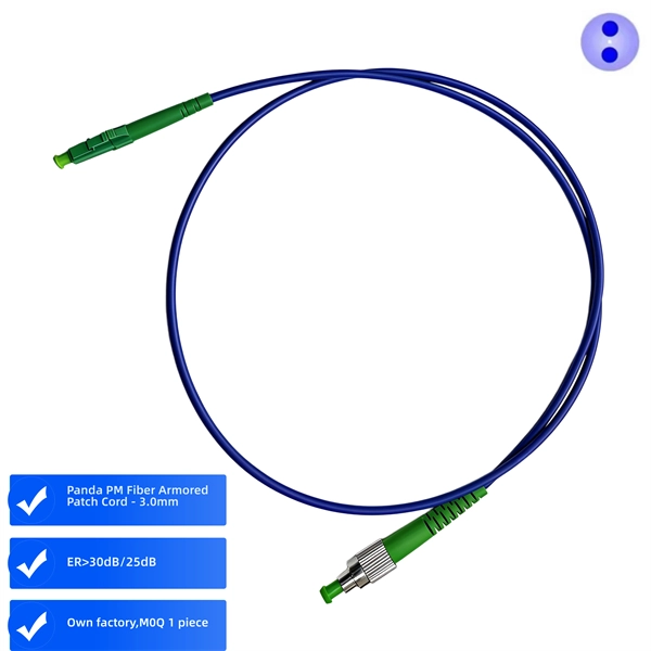
In this study, a new simulation method is proposed and verified for fiber Bragg grating patterned on polarization maintaining fiber(PM-FBG) using the transfer matrix approach. The method is designed to solv.
[PDF]
stands at the forefront of innovation with its pioneering tunable fiber Bragg grating technology. Our unwavering dedication lies in crafting state-of-the-art tunable fiber optic devices and systems with diverse applications. We specialize in custom fabrication of fiber optical gratings (FBG) across wavelengths from 400 nm to 2000 nm, tailored to precise customer specifications. Using high-power laser irradiation, we permanently modify the refractive index of the fiber core, delivering FBGs with low optical loss and. Optical Gratings are optical components that consist of a periodic structure of parallel slits or grooves etched or ruled onto a substrate material. The leading manufacturers of Gratings are listed below. Narrow down on the list of companies based on their location and capabilities. Products include phase masks, fiber optics based sensor and system, partial discharge and twin grating cavity sensors. Gould Fiber Optics is estimated to have 50-99 employees. Our patented fiber. TECHNICA focuses on Fiber Bragg Gratings (FBG) based products. Implementing our Mission we deliver the highest quality, most reliable, and. Explore 16 top manufacturers and suppliers of Fiber Bragg Gratings in our comprehensive photonics buyers' guide. A fiber Bragg grating is a type of optical filter that is inscribed or "written" into the core of an optical fiber. It consists of a periodic modulation of the refractive index along the.
[PDF]

Recommendation ITU-T L. 12 specifies splices of single-mode and multimode optical fibres. It describes suitable procedures for splicing that should be carefully followed in order to obtain reliable splices between single optical fibres or ribbons. Typical applications of these methods include aerial, buried, and underground splices. (2) American National Standard Institute/National Fire Protection Association (ANSI/NFPA) 70, 1993. § 1755. 370 - RUS specification for seven wire galvanized steel strand. 400 - RUS standard for. ation or liability to users of this publication. Existence of a standard shall not preclude any member or nonmember of NECA or FOA from specifying or using alternate construc Code (NEC) in effect at the time of publication. Because they are quality standards, NEIS® may in some instanc s go beyond. RUS standard for splicing copper and fiber optic cables. (FOA) was founded in 1995 to help develop the workforce to build the fiber optic networks to support a rapid expansion in communications and the Internet. The charter of the FOA was to promote professionalism in fiber optics through education, certification, and.
[PDF]

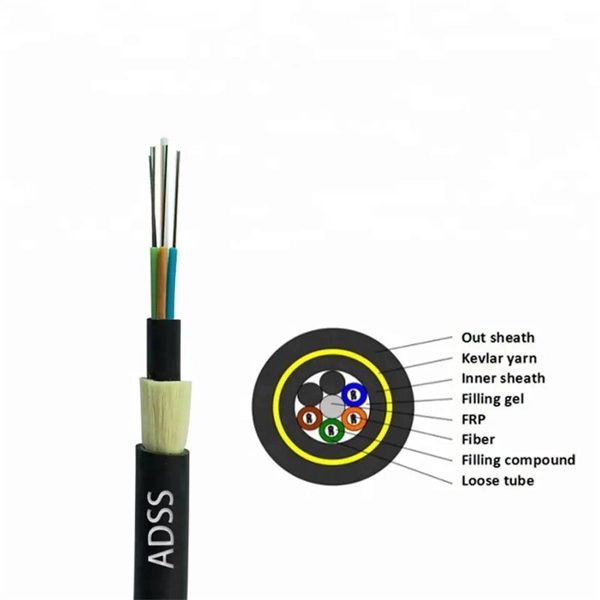
This article provides a detailed technical comparison between fiber optic and copper cables, offering a clear perspective for engineers, network architects, and procurement managers. The core distinction between the two technologies lies in the physics of data. There are significant differences in performance between ADSS cables (all-dielectric self-supporting optical cables) and traditional optical cables, which are mainly reflected in the following aspects: 1. This type of fiber optic cable is designed to support its own weight without the need for additional support structures like messenger wires. The ADSS. There are several factors to assess when deciding which cable type is right for your application, including speed of connection for new customers, ease of changes and repairs, installer certification requirements, and the ability to expand the network over time. ADSS Fiber Optic Cables are a type of optical fiber cable designed specifically for. All-dielectric self-supporting (ADSS) cable is a type of optical fiber cable that is strong enough to support itself between structures without using conductive metal elements. It is used by electrical utility companies as a communications medium, installed along existing overhead transmission.
[PDF]
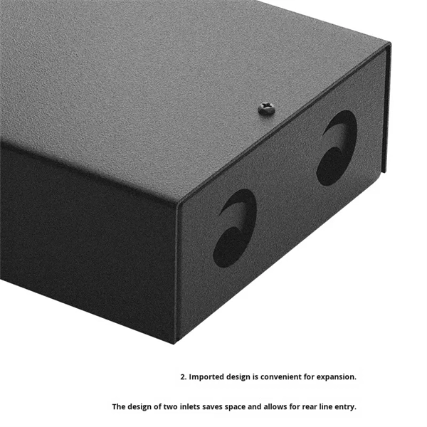
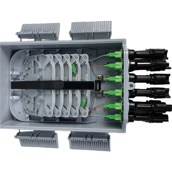
A fiber optic termination box is an enclosure designed to terminate incoming optical fiber cables and distribute optical signals to drop cables or patch cords. It integrates fiber splicing, adapter management, and cable protection in one compact unit. It is widely deployed in FTTH, FTTB, and other access networks to ensure stable signal transmission from backbone cables to end. ■ What is a Fiber Access Terminal (FAT)? A Fiber Access Terminal (FAT), also known as a Fiber Access Terminal Box (ATB) or Fiber Distribution Terminal (FDT), is a key component found in optimized fiber optic access networks for FTTH implementations. It acts like the "central nervous system". Fiber termination boxes play a vital role in ensuring efficient and reliable fiber management in FTTH applications. By understanding the components, types, and differences between various fiber management devices, businesses can make informed decisions when deploying and maintaining their fiber. But what exactly is the purpose of a fiber optic terminal box, and why is it so crucial in the realm of optical communication? First and foremost, a fiber optic terminal box serves as a robust protective shield for fiber optic cables and their delicate connections. It offers higher reliability and more flexible deployment and configuration than traditional terminal boxes. It is usually installed on the wall in the user's room or on the rack in the telecom room, and.
[PDF]

Over time, the constant expansion and contraction can make these cables brittle, increasing the risk of breakage, especially at joints and connectors. Ice accumulation is another significant concern in freezing weather. Fiber optic cables are the backbone of modern high-speed data transmission, offering unparalleled speed and reliability compared to traditional copper wires. Many advantages come with installing fiber optic cables over traditional copper cables, but that doesn't mean they are invincible. Fiber optic cabling problems with extreme cold happen when water finds its way into the ducts housing the cables. If water has the chance to enter into. Cold weather can affect fiber optic cables, but they are generally more resilient to temperature extremes compared to other types of cables, such as copper. Here's how cold weather can. For example, Bulgin's 4000 Series Fiber connector is the smallest sealed standard interface connector on the market. The fiber connection is UV resistant, salt spray resistant and sealed to IP66, IP68 and IP69K, while still providing an industry-standard LC interface as specified by IEC 61754-20. It's also widely utilized in telecommunications services, including the internet, television, and cellphones. Fiber optic internet connections are more popular globally because they provide various benefits over regular.
[PDF]
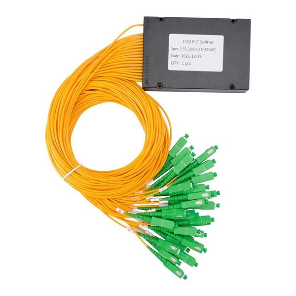
Find all you need for professionally buying wavelength division multiplexing devices: a comprehensive expert-curated directory of suppliers, scientific and technical background information, and an interactive AI-based tool with guidance for a structured decision process. A multiplexer is a digital device that combines several inputs into one line. The number of input lines to be multiplexed depends on the select lines' capacity. A mux makes it easier to convey data in systems that need multiple signals to be transmitted over a single medium. You appear to be visiting. We produce fiber-coupled Wavelength-Division Multiplexing (WDM) devices that combine (Mux) or separate (DeMux) multiple wavelength channels into or from a single optical fiber. Two types are available: integrated arrayed waveguide gratings (AWG), offering low cost, compact size, and precise ITU. WDM AWG CWDM4 module is based on silicon chip technology. It has compact, easy-to-assemble structure and good reliability. It can replace TFF (thin film filter) type CWDM. It is widely used in 40G and 100G high-speed active optical modules for optical signal Mux and Demux, such as QSFP+, QSFP28. wdm module is a truncation for Wavelength-Division Multiplexing, and is currently one of the most broadly involved innovation for high-limit optical correspondence systems. At the transmitter side, wdm module has numerous optical transmitters - each emanating at an alternate frequency -.
[PDF]

Shop DigiKey's large in-stock selection of Fiber Optic Attenuators. View inventory, pricing and order now for same day shipping!. Fiber optic attenuators are devices used to reduce or monitor the power level of a fiber optic signal. Basic types of fixed attenuation include single mode, dual window and multimode in D4/PC, FC, FC/UPC, MU, SC, SC/APC and UPC, ST and ST/UPC style connectors. Optical attenuators usually work by. FS fixed and variable fiber optic attenuators with leading attenuating fibers guarantee consistent and stable fiber attenuation (0~60dB) in WDM transmission. Thorlabs has a wide variety of single mode (SM), polarization-maintaining (PM), or multimode (MM) fixed and variable optical attenuators (VOAs). We offer SM and PM electronic VOAs that provide control of the output power with FC/PC or FC/APC connectors. Our SM and PM manual VOAs are available. Fibertronics, Inc. These attenuators are suitable for use in single mode 9/125, multimode 50/125, and multimode 62. This ensures optimal signal levels across fiber networks, preventing receiver overload and maintaining data integrity. These attenuators are essential. Attenuators are used to weaken or control a transmitted optical signal and preserve the quality of that signal when the laser or VCSEL is too strong for the receiver to read correctly. Attenuators are available in several styles and they can have either fixed levels of attenuation or they can be.
[PDF]

Optical Fiber Communication (OFC) revolutionizes modern telecommunications, enabling rapid data transfer across long distances with minimal signal loss. This comprehensive review explores OFC's historical evolution, core principles, components, and versatile applications. It traces OFC's. Additionally, optical fiber is lightweight and less susceptible to noise (no electromagnetic induction). Optical fiber consists of a cylindrical core that propagates light and a concentric cladding that surrounds it. The cladding's refractive index is slightly smaller than that of the core, which. Fibre optics and optical communications is the use of thin strands of glass for sending information encoded into light over long distances. Total internal reflection prevents light inserted into one end of the fibre from escaping through the sides. Keywords: Optical fibers, communication systems, data. Figure 1: Illustration of the inverse-square law of light intensity – the light's intensity diminishes with the square of the distance, which free-space optical signals must overcome (leading to very weak reception at long range) Figure 1 illustrates how light intensity decreases as distance.
[PDF]
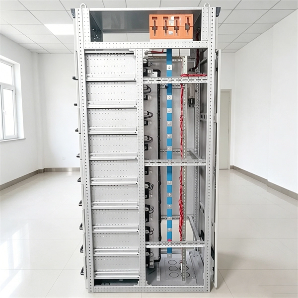
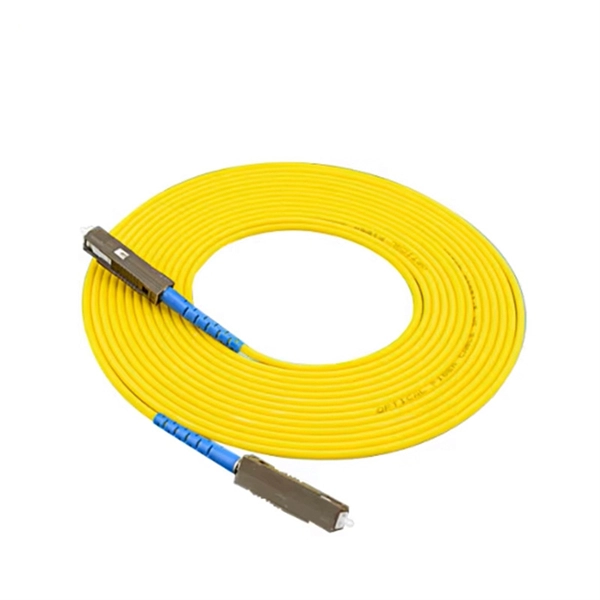
FC-FC Type: Commonly known as circular to circular tail fiber, typically used for jumpers between ODF racks. At the first step of phage infection, the receptor-binding proteins (RBPs) such as tail fibers are responsible for recognizing specific host surface receptors. The proper folding and assembly of tail fibers usually requires a chaperone encoded by the phage genome. Despite extensive studies on phage. Bacteriophage Mu is a temperate phage known to infect various species of Enterobacteria, playing a role in bacterial mutation induction and horizontal gene transfer. This initial binding is a fundamental step that dictates whether a phage can successfully infect a particular bacterial cell. Tail. A tail fiber, also known as a fiber optic patch cord, consists of a connector on one end and a cut end of the fiber optic cable core on the other. These patch cords are primarily used to connect fiber optic cables to fiber optic transceivers (couplers, jumpers, etc.
[PDF]
The answer is no; fiber internet doesn't need a traditional modem. A standard cable or DSL modem's job is to convert electrical signals into digital data that your devices can understand. But since fiber transmits data as light instead of electricity, there's no need for that type of. Instead, fiber relies on an Optical Network Terminal (ONT) to decode the signal from the fiber lines into something usable by your devices. In this way, an ONT serves the same basic function as a cable modem. However, ONTs tend to be much larger, so they are typically installed in closets, garages. The ONU connects directly to the fiber line entering the home. l It supports high speeds, often reaching 1 Gbps or more. l. While there are 137 residential internet providers in the state, most homes only have access to 1–2 options above 25 Mbps. California accounts for 12% of the US population, with 87% of California residents living in major urban centers like Los Angeles, Sacramento, and San Francisco. Instead, an Optical Network Terminal (ONT) is required to connect your home to the fiber network. In this guide, we'll explain how fiber internet works, why a modem isn't needed, and what equipment you. Your existing cable modem won't work with fiber service, and you'll need devices specifically engineered to convert optical signals into data your devices can use. Fiber internet relies on specialized equipment to deliver its high-speed, reliable performance.
[PDF]