Explore our comprehensive SFP optical module selection guide for 2025. Learn about crucial factors like data rate, distance, fiber type, and compatibility to optimize your network performance and cost-effectiveness. Make informed decisions for your networking needs today!. SFP (Small Form-factor Pluggable) is a compact, hot-pluggable network interface module used to connect network devices (switches, routers, firewalls) to fiber optic or copper cables. They're essential for extending network distances and increasing bandwidth capabilities. Selecting the correct SFP module is not simply a matter of matching connectors. In modern Ethernet networks, choosing the wrong transceiver can result in link failures, speed mismatches, compatibility errors, or unexpected distance limitations. For network engineers, system integrators, and IT. At the core of these advanced networks are bidirectional SFP modules, also known as BiDi SFP transceivers—compact, cost-efficient devices that support high-speed data transmission and reception over a single optical fiber. By using different interfaces and single-mode or multimode fiber depending on the.
[PDF]
will introduce major upgrades to its Multi-Rail technology platform at ECOC 2025, targeting hyperscale optical transport with new efficiency, scale, and performance enhancements. Coherent Corp. SAXONBURG, PA, September 26, 2025 (GLOBE NEWSWIRE) – Coherent Corp. At the heart of the. SAXONBURG, Pa. At the heart of the. Simultaneously, coherent technology has emerged as the prevailing solution for Data Center Interconnection (DCI) applications, covering distances of 80~120km in the field of data communication. These evolving applications introduce new demands for coherent optical transceiver systems, steering the. Coherent optical module refers to a typically hot-pluggable coherent optical transceiver that uses coherent modulation (BPSK / QPSK / QAM) rather than amplitude modulation (RZ/ NRZ / PAM4) and is typically used in high-bandwidth data communications applications. Optical modules typically have an.
[PDF]
Because of their low cost, low profile, and ability to provide a connection to different types of optical fiber, SFP provides such equipment with enhanced flexibility.OverviewSmall Form-factor Pluggable (SFP) is a compact, network interface module format used for both and applications. An SFP interface on. SFP transceivers are available with a variety of transmitter and receiver specifications, allowing users to select the appropriate transceiver for each link to provide the required optical or electrical reach over. Quad Small Form-factor Pluggable (QSFP) transceivers are available with a variety of transmitter and receiver types, allowing users to select the appropriate transceiver for each link to provide the required optical reach over.
[PDF]

NPO (Near-Packaged Optics) is a transitional technology bridging traditional pluggable modules and CPO. It integrates the optical engine and GPU chip side-by-side on the same high-performance PCB or organic substrate, connected via ultra-short high-speed circuits. Its core concept is to remove digital processing units such as DSPs and CDRs from the module, constructing a purely analog "linear direct-drive" optical link. In the LPO architecture: The transmitter uses a high-linearity driver chip to directly drive the optical modulator, converting the. Near-packaged optics (NPO) helps send data faster. It puts the optical engine close to the switching chip. This makes things work better. NPO lets you upgrade easily. You do not have to redesign your whole system. It lowers energy costs. Among the emerging technologies, LPO (Linear Pluggable Optics), NPO (Near-Packaged Optics), and CPO (Co-Packaged Optics) represent three important stages in the evolution of next-generation data center optical networking. Understanding how these architectures differ is essential for designing. Traditional optical modules typically rely on DSPs (Digital Signal Processors) to handle signal equalization, retiming, and compensation, mitigating attenuation and distortion during transmission. They are not concepts at the same level, but rather.
[PDF]
Optical modules are compact devices that convert electrical signals into optical signals and vice versa. They are used in fiber optic communication systems to transmit data over long distances with minimal loss and interference. These modules typically consist of a laser or LED transmitter, a. That is, metal medium communication represented by coaxial cables and network cables is gradually being replaced by optical fiber media. Composition of Optical Modules The optical module, known as Optical Transceiver in. The Transmitter Optical Sub Assembly (TOSA) is responsible for the emission of light. Here. An optical module is a typically hot-pluggable optical transceiver used in high-bandwidth data communications applications.
[PDF]
Single fiber modules (BiDi) use one fiber for both transmitting and receiving data. This saves space and money. Dual fiber modules use two fibers. They are easier to set up and give steady communication. In DWDM implementations, each direction of communication occupies a dedicated fiber, improving the stability of the transmission. This configuration is widely adopted in traditional telecom. Single-fiber WDM (also known as bidirectional or BiDi WDM) uses one physical optical fiber strand to transmit and receive signals simultaneously—often employing different wavelengths for upstream and downstream. How It Works: Two distinct wavelengths (e., 1270 nm and 1330 nm) are used in opposite. Single fiber module also called BiDi transceiver or WDM module. It uses WDM technology to realize the bidirectional transmission of optical signals on one optical fiber. BIDI module only has 1 port, wave filtering through the filter of module, and finished the transmitting of 1310nm optical signal. While both are designed for transmitting data over fiber optic cables, SFP bidi vs duplex differ significantly in how they operate and are deployed. In this article, we break down What Is an SFP BiDi Module and SFP Duplex Module? When Should You Use SFP BiDi and When Should You Use SFP Duplex? to. It has two distinct channels or ports, TX is used for transmission and RX for reception. For example: TX1310nm/RX1550nm TX1550nm/RX1310nm. Single fiber optical.
[PDF]
The BXM, BXD, and BXJ explosion-proof distribution boxes are engineered for the safe operation and control of specialized equipment in hazardous environments. Durable Hexlon Explosion Proof Distribution Boxes and Electrical Enclosures, IECEx and ATEX certified for Zone 1 and Zone 2. Order Explosion Proof Illumination Distribution Boxes from Warom Technology, a trusted manufacturer and supplier, designed for industrial lighting automation, hazardous electrical systems, nuclear illumination, defense applications, and waterproof, dustproof environments. ◆ The explosion-proof. It is widely used in flammable and explosive gas environment such as oil exploitation, refining, chemical industry, offshore oil platform, oil tanker, etc. Ideal for marine platforms, chemical tankers, LNG vessels, and dangerous cargo wharfs, these robust distribution boxes ensure reliable. Explosion Proof Box, SUREALL Low-voltage Control Guide Driving the state of the art innovation for power distribution and control for electrical equipment in harsh and hazardous location Explosion proof box, also called explosion proof boxes, include but not limit to explosion proof electrical. We supply certified explosion proof distribution box & Atex Transformer -Appleton, ATKON, CZ, CEAG, brands for safe and reliable industrial use.
[PDF]
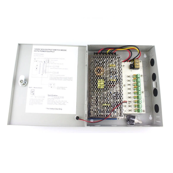
Look at key criteria like power needs, equipment type, installation conditions, safety, compatibility, quality, cost, layout, and certifications. Use practical checklists to help you make a confident decision. Calculate your total power demand before choosing a distribution. Choose the right low voltage distribution box by matching capacity, safety, and environment to your needs for reliable and efficient electrical protection. com) lists GE low voltage circuit breakers and the short circuit current to which they are selective. DET-537 includes legacy products. Designing Low Voltage (LV) and Medium Voltage (MV) electrical systems is a critical task that requires precision, knowledge, and strict adherence to international standards. The IEC (International Electrotechnical Commission) standards provide a comprehensive framework to ensure safety. Short circuit studies determine fault current levels throughout the system. This data guides protective device selection. Proper coordination prevents nuisance tripping during faults. This chapter explains the main electrical and environmental characteristics to take into account, proposes some guidelines. The safety and efficiency of an electrical system depends on the selection of an LV (Low Voltage) distribution box. The decision is influenced by numerous criteria, including but not limited to technical requirements, environmental specifications, security measures, and general product quality.
[PDF]

This guide explains how to make 90° bends, vertical bends, tees, and offsets in wire mesh cable trays safely and professionally. Horizontal 90° Bend (Flat Bend) 2. Tee (T-Junction) Bend 4. Since the jaws of the bolt cutter drags a layer of zinc across the cut end and forms a protective layer. When a wire cable tray is cut, the fact that a. Wire mesh cable trays are widely used because of their flexibility and easy on-site modification. Unlike perforated trays, bends can be created directly at site without expensive fittings. Great if you are new or just forgot how to do it, this easy to follow guide makes it so simple. more The Easy Guide to. This involves a few essential steps to ensure a successful bending process. The first step in preparing the. The method for producing bridge bend elbows is as follows: Take a 90-degree cable tray bend elbow as an example, and apply the same principles for 45-degree bends accordingly. The length of the bottom side (bottom diagonal) after bending the cable tray should be equal to the width of the cable. OTHER THAN 90 ̊ JUNCTIONS Use this guide to learn the most effective installation practices when installing Cablofil tray. Each example of bends and tee's clearly illustrate proper tray cutting combined with recommended usage of Cablofil accessories. Engineers and contractors in North America and.
[PDF]

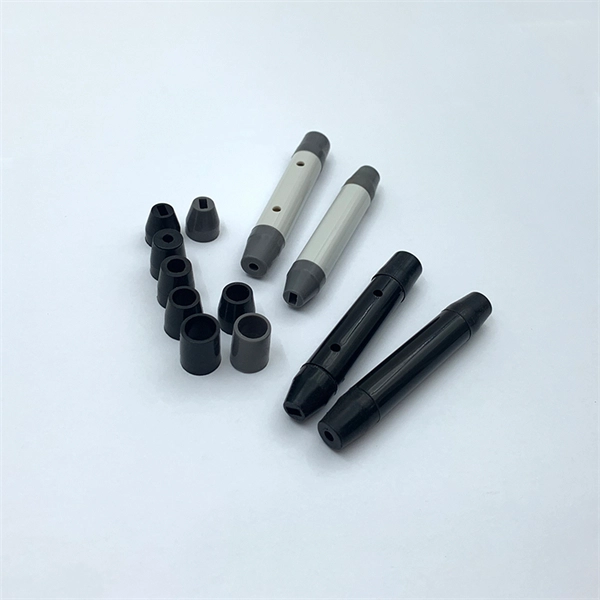
The video tutorial demonstrates the depin and repin method for repairing automotive wiring harness connectors, specifically pigtails. It outlines seven easy steps to replace a pigtail connector, making it accessible for DIY enthusiasts and individuals dealing with electrical issues. This comprehensive guide will equip you with the knowledge and skills to accurately assess the integrity of a pigtail, helping you identify issues before they escalate into larger problems. We'll explore different testing methods, delve into the interpretation of multimeter readings, and offer. The latest in the line of Ford Flex Probe Kits, this newest release includes all the probes from the previous “D” kit, but now adds two each of the Micro Pin (. Additionally, all probes will now be printed with the tip size, helping technicians ensure usage of the properly sized tip. Short answer: An automotive wiring pigtail is a short section of wire with a pre-attached connector that lets you repair or replace a damaged plug without replacing the entire harness. It provides a plug-and-play repair solution that restores OEM fit, seal, and electrical reliability. Key steps. At FindPigtails. com, we specialize in high-quality, OEM connector replacement. Why pay thousands for a complete wire harness, when you can simply replace the damaged connector? We invite you to take a look at some of our instructional videos, for step-by-step guides of de-pin and re-pin procedures.
[PDF]

This is the FOA's Online Guide To Fiber Optics, Fiber Broadband & Premises Cabling. With 19+ years of experience installing fiber-optic cables at over 20,000 locations, we've seen how prices vary based on cable type, project scope, and installation complexity. Fiber-optic cable materials typically cost $1 to $6 per linear foot, depending on fiber count and cable type. Main cost drivers include cable grade (indoor vs outdoor, armoured), distance, and labor for trenching, splicing, and termination. This guide presents ranges in USD and practical price estimates to help. Fiber optic cables are essential components in today's broadband, FTTx, and data center networks. Whether you're planning a national fiber rollout or sourcing cables for enterprise infrastructure, understanding how fiber optic cable pricing works can help you budget more effectively and make better. We have included Per Foot conversions for reference (1 Meter ≈ 3. Best For. * Disclaimer: Prices fluctuate based on raw material indices (Glass/Copper/Polymer) and cable core count (e. These cables, constructed with glass or plastic fibers, transmit data through light pulses, offering.
[PDF]

The main group of impedance relays is distance protection devices. loss of synchronism protection, loss of excitation protection, or impedance automatics like fault locator. Impedance Relay Definition: An impedance relay, also known as a distance relay, is defined as a device that triggers based on the electrical impedance measured from a fault's location to the relay. Working Principle: The operation of an impedance relay hinges on the balance of voltage-induced. When a system has too many radial lines protection using time delay overcurrent relay becomes impractical. This problem can be solved to an extent by using distance relays. Distance relays uses voltage and current to calculate the. Distance relay protection has been defined as a part of relay protection in power systems that detects and isolates faults based on the distance between the relay and fault points. Unlike overcurrent relays, which only respond to the magnitude of current, a distance relay measures the impedance of. Such relays are called Distance Relays or Impedance Relays. In an impedance relay, the torque produced by a current element is opposed by the torque produced by a voltage element. The relay will operate when the ratio V/I is less than a predetermined value. The voltage transformer measures the voltage across the protected equipment, while the current transformer measures the current flowing through it.
[PDF]
This list includes both standards-based and real-world technical cable types utilized in fiber-optic infrastructure, telecoms, enterprise, and outdoor applications. • OFC: Optical fiber, conductive• OFN: Optical fiber, non-conductive• OFCG: Optical fiber, conductive, general use.
[PDF]
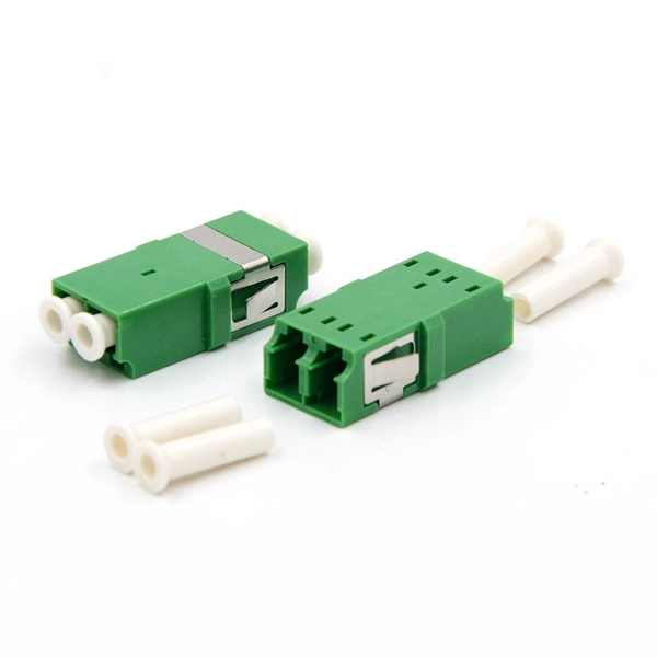
There are connectors designed for single mode and multimode fiber optic cables, which differ in core size, bandwidth, and optimal use cases as explained in this comprehensive guide to fiber optic cable.
[PDF]
Fiber optic couplers can either be passive or active devices. Passivefiber optic couplers are said to be passive as no power is required for operation. They are simple fiber optic components that are used to re.
[PDF]