7 meters) high makes it easily accessible without the need to bend or stretch excessively. This height also safeguards the box from potential water spills or accidental impacts. The proper installation of a distribution box involves placing it at the right height to ensure safety and convenience. ALL DIMENSIONS ARE CONSIDERED FROM FINISHED FLOOR AND, UNLESS NOTED OTHERWISE, SHALL NOT VARY. ALL DIMENSIONS SHALL BE COORDINATED WITH ARCHITECTURAL DETAILS AND MAY BE. Due to the long time interval between the embedding of the box and the installation and wiring of the box panel, the box shall be disassembled with the box cover (door) and the panel first, and marked for storage, so as to prevent the electrical components and the box cover (door) from damage or. TO EVERY CIRCUMSTANCE OR ELECTRICAL SYSTEM. SRP ENCOURAGES EACH USER TO CONSULT WITH ITS OWN TECHNICAL ADVISOR CONCERNING THE APPLICABILITY OF THESE TANDARDS TO THE USER'S SPECIFIC SITUATION. THE USER ASSUMES ALL RIS USE OF OR RELIANCE ON THESE SPECIFICATIONS. ALL REPRESENTAT ERIA ND FACILITIES. The exposed bottom edge of the lighting box in the basement is 1. 7m away from the ground, the installation height of the control box is 1. 2 Setting and Removing Meters - None but duly authorized agents of the Company or persons authorized by law shall set or remove, turn on or turn off, or make any changes which will affect the accuracy of such meters. Connections to the Company's system are to be made only by its employees.
[PDF]
This CAD file provides the complete fabrication and layout details for the most common type of indoor electrical enclosure. Are you designing a control panel for a new machine or a sub-panel for a building? Our Standard Power Distribution Box drawing is the essential, universal blueprint you need. High-performing, reliable product solutions that transmit data, power and signal in cars, planes, power grids, appliances, electro. Discover all CAD files of the "Power Distribution Boxes" category from Supplier-Certified Catalogs ✅ SOLIDWORKS, Inventor, Creo, CATIA, Solid Edge, autoCAD, Revit. The CAD files and renderings posted to this website are created, uploaded and managed by third-party community members. This content and associated text is in no way sponsored by or affiliated with any company, organization, or real-world good that it may purport to portray. It is running model of. Dwg-69 3GOS on 11Mtr Spun pole without Tr seating for 63,100,250kVA Tr. Please note that this page also provides links to the websites / web pages of Govt. Ministries/Departments/Organisations. Content Owned and maintained by: Bengaluru Electricity Supply Company Limited, Government of Karnataka. Development of a distribution box for a meter. Download CAD block in DWG. 22 KB). Free and premium CAD blocks, details, models, and plans for architects, engineers, and designers worldwide. © 2026 DesignsCAD. Download Electrical Distribution Box - - Prosegel DWG Block for AutoCAD.
[PDF]
Discover the most common types and models of Direct Attach Cables (DACs), including 10G, 25G, 40G, 100G, 200G, and 400G. A Direct Attach Cable (DAC) is a factory-assembled high-speed copper cable with fixed connector “module-style” ends. It's widely used for short-reach links in data centers because it delivers low latency, simple deployment, and cost-efficient interconnects-especially for rack-level connectivity. These cables come pre-terminated with SFP (Small Form-factor Pluggable) or QSFP (Quad Small Form-factor Pluggable) connectors which simplify network setup. High-speed cable is a kind of low-cost short-distance connection solution to replace optical modules. Both of its ends have cable assemblies of a module, which are connected. Direct attach copper (DAC) cables are twinax copper assemblies with fixed transceiver-like ends. They deliver high bandwidth, low latency, and great density for top-of-rack (ToR), server-to-switch and switch-to-switch connections. This article summarizes the common DAC categories and. What is a Direct Attach Copper (DAC) Cable? Common Types And Uses Summary : Direct Attach Copper (DAC) cables provide fast, reliable, and cost-effective short-distance connections for data centers, enterprise networks, and top-of-rack setups. With passive and active variants, DAC cables offer.
[PDF]

Beam splitters are classified by construction (plate, cube, pellicle, polka dot) and by function (standard, non-polarizing, polarizing, dichroic). Construction determines ghosting, damage threshold, and form factor. Function determines how polarization and wavelength are. Beamsplitters are optical components used to split incident light at a designated ratio into two separate beams. Additionally, beamsplitters can be used in reverse to combine two different beams into a single one. Beamsplitters are often classified according to their construction: cube or plate. A beam splitter (or beamsplitter, power splitter) is an optical device which can split an incident light beam (e. a laser beam) into two (or sometimes more) beams, which may or may not have the same optical power (radiant flux). It is a crucial part of many optical experimental and measurement systems, such as interferometers, also finding widespread application in fibre optic telecommunications. It is also possible to combine the separated beams. Types of Beam Splitters 2. They are found in different configurations and can be used in multiple applications. However, how they work exactly often remains overlooked. These versatile tools can split both laser and regular light, depending on the application in question.
[PDF]

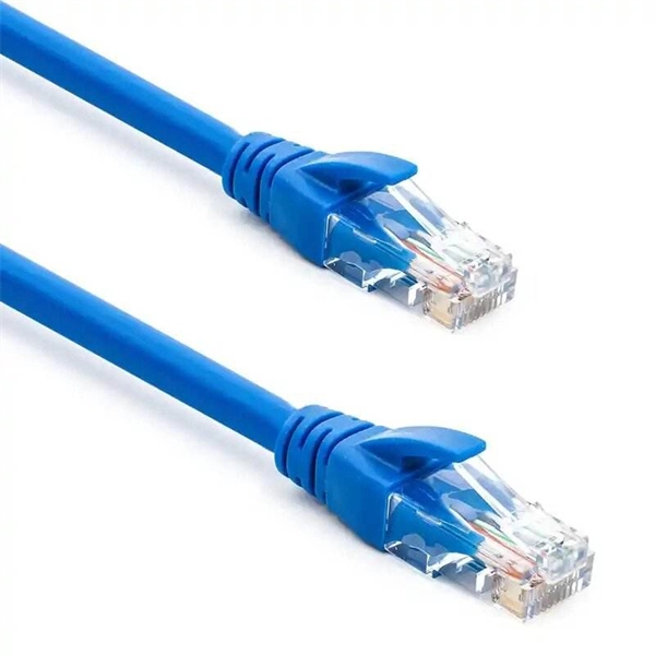
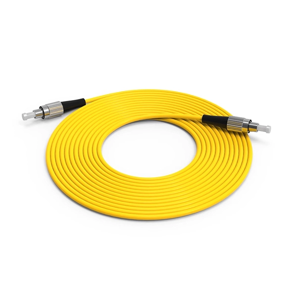
Fiber optic connectors can be categorized according to different standards such as utilization, fiber count, fiber mode, and transmission method. They are also divided into single-mode and multimode types based on their distinct characteristics. This guide will walk you through the most common fiber connector types, explaining their characteristics, advantages, and typical use cases. Whether you're planning an FTTH deployment, upgrading a data center, or working in telecom infrastructure, this guide will help you make informed decisions. Compared to Copper cables, Fiber connector types are incredibly varied. Where copper twisted pairs tend to terminate with an RJ45 plug, fiber optic connectors come in all sorts of shapes and sizes, with all manner of different use cases in mind. An optical fiber connector is used to join optical. With a wide variety of connector types available, choosing the right connector for your network can be challenging. Learn how each connector works, where it's used, and how to choose the right option for today's high-density, high-speed networks. It is a precise coupling device that joins fiber optic cables quickly, enabling faster connection and disconnection than splicing. The connector mechanically orients the fiber cores, allowing light to pass and travel through. In this guide, you'll explore various types of fiber optic cable connectors, each with unique features and best uses. We'll also provide practical advice.
[PDF]
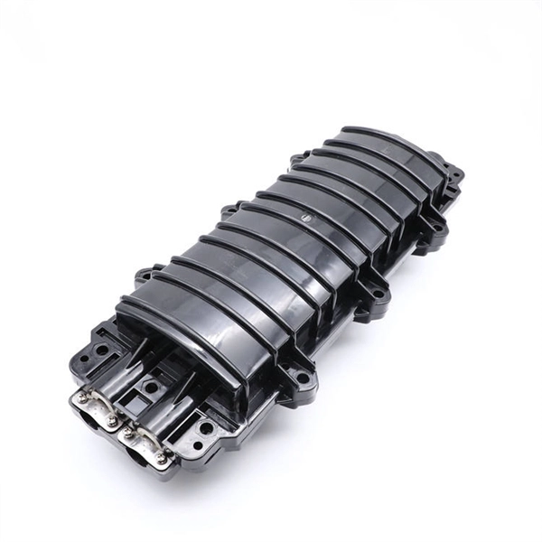
Fiber optic couplers can either be passive or active devices. Passivefiber optic couplers are said to be passive as no power is required for operation. They are simple fiber optic components that are used to re.
[PDF]
Explore all types of cable trays—ladder, perforated, basket, solid, and channel. Each cable tray type performs a different function and comes in various materials such as aluminum, galvanized steel, and FRP. What is Cable Tray? 1. Non-Metallic What is Cable. Cable tray systems are engineered support structures designed to route, support, and protect insulated electrical cables used for power distribution, control, instrumentation, and communication. Unlike conduit systems, cable trays allow cables to be laid in bundles, improving accessibility, heat. Below are the top 7 types of cable trays and their applications, along with their key advantages. Ladder Type Cable Tray The ladder type cable tray consists of two side rails connected by rungs, allowing excellent airflow around cables. Ladder cable tray is so named because it resembled a ladder. Ladder cable trays are relatively simple in. Selecting the correct cable tray for low voltage system—such as data networking, telecommunications, security, and building automation—is a critical decision that impacts system performance, scalability, and long-term reliability.
[PDF]
A temporary power box, also known as a power spider box, is a portable electrical enclosure that provides temporary electrical power distribution on construction sites and other remote locations. It serves as a hub for connecting various electrical loads and distributing power. Temporary construction power system s are essential for delivering safe and reliable electricity across dynamic job sites. From powering heavy machinery to supporting lighting and tools, temporary power boxes must operate in harsh outdoor conditions while ensuring electrical safety and flexibility. These panels act as the central. Temporary power distribution boxes provide a safer way to manage power while keeping your workspace tidy. These versatile units work great for construction sites, entertainment events, and disaster recovery operations. You can use them to power electrical equipment, lighting systems and more. Unlike permanent power solutions that are integrated into a building's.
[PDF]
Picking up the best router for fiber internet isn't just about going to the market and choosing one of the best wireless routers. Instead, you need to carefully look at its specs, performance, and the type of securit.
[PDF]
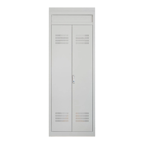
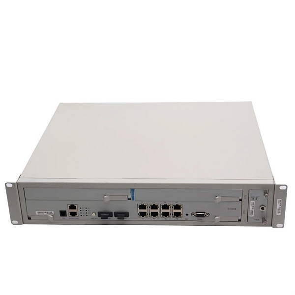
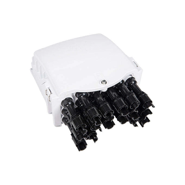
A distribution box serves as a critical component in fiber optic networks. This device provides a centralized location for terminating and connecting fiber optic cables, ensuring reliable and efficient connectivity between network components. They serve as hubs where fiber optic cables are connected, managed, and distributed to end-users. As digital connectivity demands grow, these boxes are becoming more versatile and widespread. From. Optical fiber distribution box plays a key role in the power system and optical fiber communication network, and its main functions can be summarized as follows: First, signal transmission and connection 1. Optical fiber cable connection: The main function of the optical fiber distribution box is. In FTTH, FTTB, and other fiber access networks, terms such as Fiber Optic Termination Box, Fiber Distribution Box (FDB), and ODF (Optical Distribution Frame) are frequently mentioned. Although all three are related to fiber connection and management, their installation locations, functional roles. Optical Distribution Frames (ODF) are indispensable components in optical communications networks.
[PDF]
All interval wiring should conform to the relevant International Best Practices. For general site work additional precautions are necessary. Other than supplies for welding purposes, cables carrying a voltage to earth in excess of 65V should have co. All interval wiring should conform to the relevant International Best Practices. For general site work additional precautions are necessary. Other than supplies for welding purposes, cables carrying a voltage to earth in excess of 65V should have continuous metal armour or sheath which has been effectively earthed. Where trailing cables are concern. An RCD or ELCB is to be installed to all final distribution boards and tested before use on each shift. To allow only the use of 110 volt for portable electric tools. Earth Leads Earth leads must be colored yellow and green, and yellow should be of stranded copper or copper alloy with a cross section of at least 6 sq.mm. The maximum size need not e. All extension cables / cords should have a current inspection tag affixed and should be checked for damage prior to use. Extension cables / cords in one office should not be used to supply power to another office, building or adjacent offices. Cables / Cords may not run through doors, windows or ceilings unless for the purposes of temporary constru.
[PDF]

The main group of impedance relays is distance protection devices. loss of synchronism protection, loss of excitation protection, or impedance automatics like fault locator. Impedance Relay Definition: An impedance relay, also known as a distance relay, is defined as a device that triggers based on the electrical impedance measured from a fault's location to the relay. Working Principle: The operation of an impedance relay hinges on the balance of voltage-induced. When a system has too many radial lines protection using time delay overcurrent relay becomes impractical. This problem can be solved to an extent by using distance relays. Distance relays uses voltage and current to calculate the. Distance relay protection has been defined as a part of relay protection in power systems that detects and isolates faults based on the distance between the relay and fault points. Unlike overcurrent relays, which only respond to the magnitude of current, a distance relay measures the impedance of. Such relays are called Distance Relays or Impedance Relays. In an impedance relay, the torque produced by a current element is opposed by the torque produced by a voltage element. The relay will operate when the ratio V/I is less than a predetermined value. The voltage transformer measures the voltage across the protected equipment, while the current transformer measures the current flowing through it.
[PDF]
NF C 15-100, also known as the C 15-100 standard, is the French electrical regulation for low-voltage (LV) installations. It sets out the rules imposed on electricians for electrical installations in residential buildings (detached houses, flats, etc). The standard domestic electricity supply in France is single phase 230 volts, 50Hz. It is also common to find a 3–phase 380v distributed supply in larger properties. It must be applied to all new work and.
[PDF]
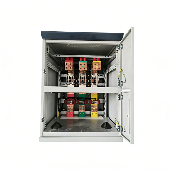
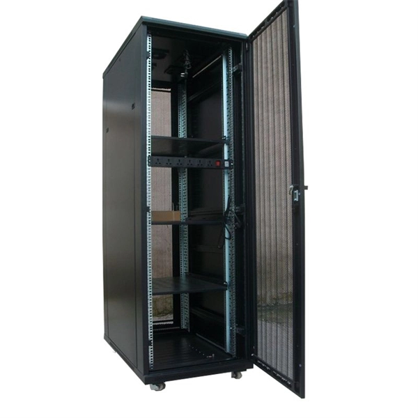
Choose the right box based on environment (indoor/outdoor), load capacity, and durability. Check for proper IP/NEMA ratings and material quality. Ensure safe placement: install in dry, accessible areas with good ventilation and at appropriate height (typically ~1. Practice good wiring: secure. Whether you are an electrical contractor or a construction brigade, knowing how to properly and safely install distribution boxes is the basis of ensuring the safe operation of the entire system. This article details the process of installing them, which helps you comprehend distribution boxes. Electrical systems power our homes, offices, and industrial facilities, but behind every reliable electrical setup lies a crucial component that often goes unnoticed: the distribution box. This essential piece of equipment serves as the nerve center of your electrical system, managing power flow. Everything you need about the wire and cable market, visualized. NEC Article 314 establishes requirements for the installation and use of electrical boxes, conduit bodies, fittings, and handhole enclosures. Whether it is residential buildings, commercial facilities or industrial sites, the. Publish Time: 03/08 2025 Author: Site Editor Visit: 918 The installation requirements and specifications of Distribution box involve many aspects, including site selection, fixing method, wiring specifications and safety protection. Site selection requirements: The distribution box should be.
[PDF]

Start by examining the plastic cover closely to identify any tabs or locking mechanisms that may be holding it in place. This robust enclosure houses either the main service disconnect or a sub-panel, acting as a control point for electricity distribution to the property or a dedicated outdoor system like a pool or workshop. Gaining access to the panel's interior is usually necessary for simple tasks like resetting a. Opening electrical boxes outside can be a tricky endeavor. Without the proper tools, knowledge, and safety measures, it can also be dangerous. However, with a few simple steps, you can open an outdoor electrical box safely and efficiently. This is how you can open them to have access to the plug-ins. Once you've loosened the. This guide will explore the steps and considerations for safely and effectively punching out a plastic electrical box. Ensure the wires are not powered before starting work. Flat-head screwdriver, electrical pliers, hammer, and a suitable meter or tester. Locate. Before you attempt to open an outdoor breaker box, it's crucial to prioritize your safety. Here is a set of guidelines to ensure you undertake this task without any hazards: Confirm power is disconnected to the unit by turning off the main breaker or disconnecting the main fuse.
[PDF]