Main distribution boards (MDB) manage and distribute electrical power from one or more sources to branch circuits in an LV distribution system. It provides circuit breakers for each branch circuit to prevent faults and incidents. Panelboards are designed to meet UL 67 and NEMA Standard PB1. What is the difference between a switchboard and a panelboard? Switchboards and panelboards provide a similar functionality in a power distribution system. Panelboards are typically flush mounted or surface mounted and are limited to a. A distribution board (also known as panelboard, circuit breaker panel, breaker panel, circuit breaker, electric panel, fuse box or DB box) is a component of an electricity supply system that divides an electrical power feed into subsidiary circuits while providing a protective fuse or circuit. According to NEC Article 100, branch circuits are the conductors between the final overcurrent device protecting the circuit and the outlet. This article deals with lighting and appliance branch circuits. The article also covers motors or. A panelboard is a distribution assembly designed to divide an incoming electrical feed into numerous smaller branch circuits. Each circuit is protected by its own circuit breaker. Inside a distribution box are components. multiwire). Branch device and terminates at another circuits are usually low current (30 amps or distribution center, panelboard, or load less), but can also supply high curre ts.
[PDF]
Abstract: In this paper, a comprehensive study on erbium-doped fiber amplifier (EDFA) characteristics under temperature variation has been performed. The rate and propagation equations that characterize EDFA performance pumped at 980 nm and 1480 nm in the forward direction are solved numerically. The. The EDFL serials of erbium-doped fiber amplifier features a very short latency for applications which require minimum signal delay. The EDFL is built using semiconductor lasers, WDM, isolator, and erbium-doped fiber. The product has the advantages of high reliability, high power output, high gain. The world first plug and play SFP+ -EDFA, FOA is a full-functioning EDFA module with control circuitry packaged inside. It is totally compatible with conventional SFP+ optical transceiver in respect of size and pin-map. The first trans-Pacific optical cable employing EDFAs, launched in 1996, enabled stable amplification of multiple wavelength channels across thousands of kilometers without electrical regeneration. This innovation eliminated the need for thousands of electrical repeaters, significantly reducing. Erbium Doped Fibers provide the basic building blocks for fiber optic amplifiers more specifically Erbium Doped Fiber Amplifiers (EDFAs) used in broadband optical networks and CATV applications. The core of the fiber is doped with Erbium and is typically pumped with 980 or 1480 nm to produce gain.
[PDF]
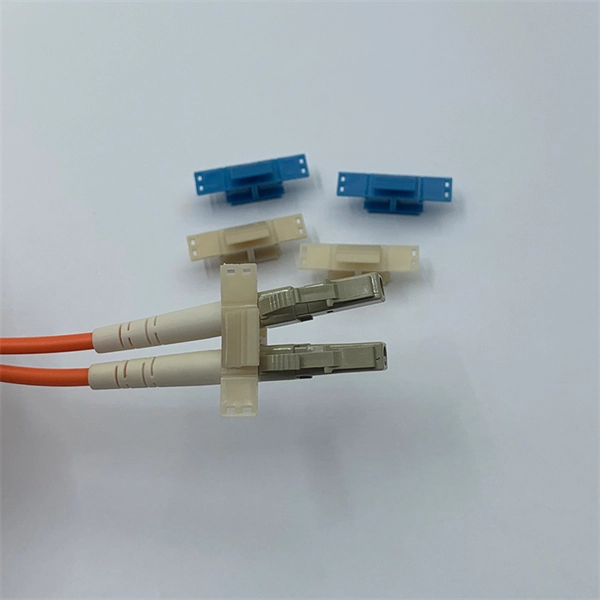
In the rapidly evolving landscape of modern networks, fiber optic connectors play a pivotal role in ensuring seamless data transmission and connectivity. These essential components bridge fibers, enabling the efficient transfer of information across various applications and. Among these components, fiber connector types are essential to network performance, reliability, and scalability. This guide will walk you through the most common fiber connector types, explaining their characteristics, advantages, and typical use cases. The connector body, which is the protective housing that holds and protects the ferrule, plays a key role in ensuring a robust and durable connection. Fiber optic connectors can. Whether it's for internet networks, telecommunications, or data centers, fiber optic cables rely heavily on connectors to establish secure and efficient connections. They link fiber optic cables, allowing data to move quickly with minimal loss. In this guide, you'll explore various types of fiber optic cable connectors, each with unique features and. Learn about the top 4 fiber optic connectors (LC, SC, ST, MTP/MPO) and find the best options for your network, optimizing performance, reliability, and data transfer in a technological age.
[PDF]

This complete guide explores everything you need to know about ODFs — from their structure, types, and key components, to installation best practices and modern design trends. Clients facing the exact demands of specialized environments—whether it's ultra-low-latency AI clusters, space-constrained military installations, or high-density telecom exchange points need more than off-the-shelf cabling. At FS, we place the customer at the heart of our operations. We are. This white paper provides a comprehensive guide to designing future-proof fiber optic networks, emphasizing a core-to-edge architectural approach. Key focus areas include backbone topologies, optical loss budgeting, standards compliance, and strategies for optimizing high-density environments like. In modern data centers and enterprise networks, Optical Distribution Frames (ODF) serve as the backbone for organizing, terminating, and managing fiber optic connections. As data centers, enterprises, telecom operators, and smart-building infrastructures deploy increasingly dense fiber links, ODFs provide the structured. Fiber optic network design refers to the specialized processes leading to a successful installation and operation of a fiber optic network. It includes first determining the type of communication system (s) which will be carried over the network, the geographic layout (premises, campus, outside.
[PDF]

It connects to two independent power sources, enabling automatic switching to a secondary source during primary source failures. This seamless transition prevents disruptions to connected devices and enhances operational reliability. A dual power switching box is precisely the kind of gadget that guarantees a constant flow of electricity as it enables the user to shift the operational state between two different energy supplies. It can be found in homes, workplaces, factories, and anywhere else where sudden cuts of energy can. The ATS Dual Power Distribution Box plays a pivotal role in providing efficient low-voltage power solutions, ensuring that power flows seamlessly, even in the event of an outage. This comprehensive guide offers insights into the mechanisms and benefits of the ATS Dual Power Distribution Box. Transfer switches and sub panel boxes are key components in dual power switching cabinets. Transfer switches automatically switch between power sources during outages, ensuring uninterrupted power and system reliability. This redundancy ensures that if one power source fails, the other can immediately take over, minimizing downtime and preventing. A dual power switch helps you manage two power sources for one system. You can use it to keep your equipment working if the main power stops. This device quickly changes from the main supply to a backup source. This seamless transition.
[PDF]

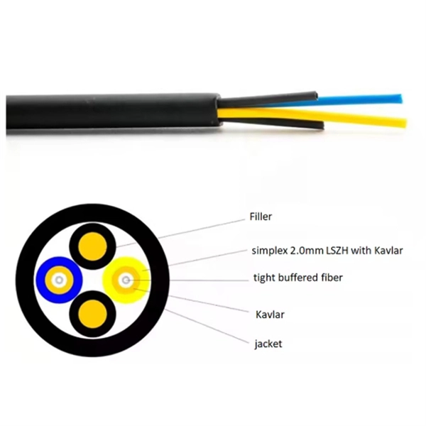
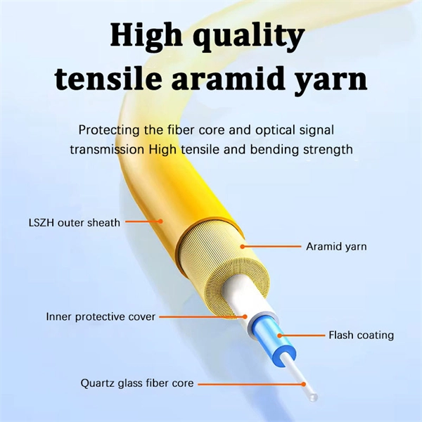
Multi-mode fiber optic patch cords utilize a larger core size, typically around 50-100 microns, allowing them to carry multiple modes of light. This design enables the transmission of data over relatively short distances with high bandwidth capabilities. A fiber-optic patch cord is a fiber-optic cable capped at each end with connectors that allow it to be rapidly and conveniently connected to telecommunication equipment. This is known as interconnect-style cabling. A fiber-optic patch cord is constructed from a core with a high refractive. These short fiber optic cords connect transceivers, switches, patch panels, and servers. Without them, even the best optical modules and switches cannot deliver performance. As data rates increase from 10G → 100G → 400G → 800G, patch cables must handle more bandwidth, more density, and stricter. Fiber optic patch cords, also known as fiber optic patch cables or fiber jumpers, are indispensable components in modern optical networks. They act as the critical link for interconnecting devices like optical switches, servers, and distribution frames. Understanding the various technical. Fiber patch cables, also called fiber-optic patch cords, are cables typically containing one or two optical fibers, which are equipped with standardized fiber connectors on both ends. The function of the fiber patch cord.
[PDF]

Sensitivity Test: Confirms that the protection works properly for internal defects in the protected zone. Inject primary current via one set of CTs, with one current flowing inward & the other outward. If the CTs are properly connected, there should be no operating current at the. A protective relay is basically an electrical device that detects a fault in a power system and initiates the operation of the circuit breaker to isolate the defective section or component from the rest of the system. In other words, the prime function of protective relays is the timely and. To conduct the tests effectively the following devices and equipment are required: Primary Injection Test Kit – for injecting large currents directly into CT circuits. Secondary Injection Test Kit – Simulates relay inputs with the controlled currents and voltages. It emphasizes selectivity, coordination, fault response, and system behavior rather than individual relay devices. This prevents damage to equipment, reduces downtime, and safeguards. This handbook covers the code of practice in protection circuitry including standard lead and device numbers, mode of connections at terminal strips, colour codes in multicore cables, dos and donts in execution. Its main purpose is to safeguard electrical equipment like transformers, generators, and transmission lines from damage due to.
[PDF]

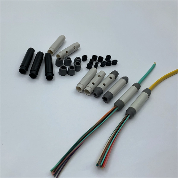
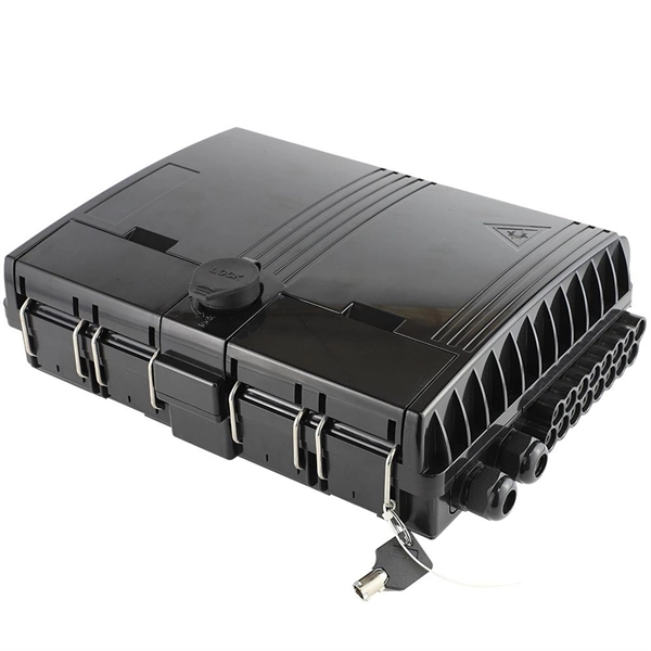
At its core, a fiber termination box combines hardware and software components to facilitate fiber optic connections. The hardware includes protective enclosures, splice trays, adapters, connectors, and patch panels. A Fiber Terminal Box (FTB) is a customer-side termination and distribution device used at the end of the optical network. It is small, so it is considered a mini version of the optical distribution frame or optical distribution frame (ODF). The number of ports of fiber optic junction boxes ranges from 8. A fiber optic junction box, also known as a fiber optic distribution box or termination box, is a protective enclosure that facilitates the connection and management of fiber optic cables. It serves as a central point for organizing and distributing optical fibers, ensuring efficient connectivity. Fiber termination boxes are essential components in modern telecommunications infrastructure. They serve as the critical junction points where fiber optic cables connect, splice, and distribute data signals efficiently and securely. Here's a structured breakdown. This article provides an in-depth comparison of fiber terminal boxes and junction boxes to help clarify their differences and deepen your understanding.
[PDF]
The term “hot” indicates that the bus bar is energized and constantly carrying electrical current, typically 120 volts relative to the neutral connection. This energized state makes the bus bar a direct interface between the incoming service and all the individual. The function of the bus bar is direct and clear: to convey power (as high current and/or high voltage) from the source to the load with an acceptably low voltage drop and power loss. This means using solid bars of copper (sometimes aluminum) with a cross-section size that keeps resistive losses and. A hot bus bar is a component within a residential electrical panel, often called a breaker box or load center. The bus bar is a thick metal strip that acts as the primary highway for distributing utility power throughout a home's wiring system. Code Change Summary: A new code section requires barriers at specific feeder terminations. In technical terms, a busbar is: You typically see busbars made from: Why Busbars Instead of Cables? You use busbars. New section requires barriers over uninsulated ungrounded busbars or terminals that are exposed in panelboards, switchgear, or motor control centers. Barriers shall be placed such that no energized uninsulated, ungrounded busbar or terminal is exposed to inadvertent contact by.
[PDF]
5mm (SC/ST/FC/E2000) versions, this pen is a must-have maintenance tool for engineers in fiber optic networks, ensuring stable performance and low insertion loss. Price and other details may vary based on product size and color. 25mm LC Fiber Cleaner Pen. LCUPC Optical Connector Cleaner & Endface Cleaning Pen Comes with Damage Protection Case & Dust Caps Need help?. The HTO9-CPM250 Mini Fiber Optic Cleaner Pen is a compact, high-precision tool designed to clean contamination from fiber connector end-faces. With an ergonomic push-action design, it efficiently removes dust, oil, and debris from both adapter ports and connector plugs without using alcohol or. This is a 1. 25mm One-Click Fiber Optic Cleaning Pen that is great for quickly removing dirt, dust, oil, and grease from optical fiber adapters. It is designed to clean LC and MU connectors. This fiber optic cleaning pen is great at cleaning hard-to-reach areas, ferrule end-faces and inside the plug. The Best applications for this cleaner are Fiber network panels and assemblies, Outdoor FTTX applications, Cable assembly production facility, Testing laboratories Server, switches, routers, and OADMS with SC, ST, and FC interface. SC Fiber Optic Cleaner Pen is designed to specially work well with. Despite its light weight and compact size, the fiber optic cleaning pen can clean over 1000 connector end surfaces with just one unit. Designed for SC, FC, ST (2. High-Performance Cleaning.
[PDF]