A 4 Core Optical Cable is a fiber optic cable that contains four individual optical fibers within a single protective outer jacket. Each fiber is capable of independent data transmission. A TOSLINK optical fiber cable with a clear jacket. These cables are used mainly for digital audio connections between devices. A fiber-optic cable, also known as an optical-fiber cable, is an assembly similar to an electrical cable but containing one or more optical fibers that are used to carry. This guide covers everything you need to know about 4 core fiber, including its internal structure, TIA standard color coding, and how to choose the right type. They are ideal for long-distance communication and. But generally, the cable core, strength member and outer sheath together make a fiber optic cable. It transmits electricity or information from one place to another. These fibers are used to transmit data as light signals, offering high-speed data transfer capabilities over long distances with minimal loss. Fiber optic cables are crucial.
[PDF]
This article provides a detailed guide on how to wire a generator into a breaker box along with the necessary equipment and safety precautions. Choose Transfer Method 2. Select the Generator 3. But once you have a generator sitting in your garage, the next big question is how to get that power into your home safely. In this guide, we'll walk through the basics of wiring a generator to your breaker box, step by step. We'll cover the equipment you'll need, the safety rules you can't skip. Connecting a wire generator into a breaker box is a critical process for safely powering your home during a power outage. This procedure involves integrating a portable or standby generator with your home's electrical system through the breaker box, often called the main panel. Ensure you use a double-pole breaker and interlock kit with following proper safety protocols. Unlike a standard plug, which can only handle a limited amount of power, a generator plug can handle higher voltages and currents, making it ideal for powering up. However, connecting a generator to your breaker box can be a complex and potentially dangerous task if not done properly.
[PDF]

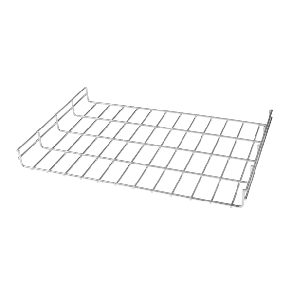
This section provides an overview for wire mesh trays as well as their applications and principles. Here are the top-ranked wire mesh tray companies as of May, 2026: 1. Code Electric Products Ltd. Attaches wire mesh tray to strut without bolts and nuts or tools. Hot dipped Galvanized Finish for exterior use Universal Dropout Kit- side mount 12" cable dropout in electrozinc. 12" Center Hanger - Only one threaded rod is needed to suspend tray. Suspension tube protects cables. Other products such as frames, handles, guides, cable rings, shelves, baskets, racks, cable management panels, container holders, shelf dividers & sterilizer carts are available. is estimated to have 10-49 employees. How can we improve? Choose from our selection of wire mesh trays, including over 475 products in a wide range of styles and sizes. Same and Next Day Delivery. Marlin Steel's wire mesh cable trays are designed for high-performance cable management in data centers, industrial manufacturing, power distribution systems, and commercial infrastructure projects. Engineered for durability and airflow, our systems provide a robust, flexible, and easy-to-install. North American cable tray systems have strict standards. These focus on durability, safety, and easy installation. Choosing a supplier that follows these standards ensures your cable management system meets high quality. It also provides long-term performance and safe operation. This guide will.
[PDF]

Use your pliers to twist the pigtail wire and the ground wire together. Snip the sharp edge at the terminal and then insert it into the wire cap. If your metal box is in use, secure a green screw in the threaded opening at the back of the metal box. In this guide, I will teach you how to pigtail ground connections in metal and electrical boxes, and how to make a perfect pigtail. Below I will provide straightforward. Pigtailing is an essential electrical wiring technique used when adding devices or when there aren't enough spaces in a junction box. 📌 What You'll Learn in. If you have a pigtail for three wires (say # 14 AWG if that makes a difference) together in a wire nut but you want to add another wire to the mix. Is the proper method to undo the wire nut and untwist them and try to straighten out all three as best as possible? (In IT there was a tool to. Before diving into the mechanics of twisting, it's crucial to understand the two primary components involved: the wire itself and the pliers you'll be using. The success and durability of your twist depend heavily on selecting the appropriate materials and tools for the job. This technique is often employed when three or more wires need to be joined, ensuring that the. A pigtail wire is a short cable used to lengthen short wires. Also, it can join several wires to become a single conductor for electrical connections. The National Electrical.
[PDF]

The maximum distance of copper is around 328 feet (100 meters), which is a far shorter range than is offered by either of the fiber optic cable types. This is because fiber optic cable is not affected by attenuation, dispersion, or EMI in the same way that copper is. Many factors decide the fiber cable distance, but the key factors include the below six aspects. Attenuation First is the attenuation of the optical fiber. For some. Fiber optic cable transmission distance is determined by two primary physical factors that affect signal quality as light travels through the fiber medium. The selection of fiber optic cables over copper wires or vice versa depends on factors such as bandwidth, distance, and cost of transmission. Fiber optic cables transmit data using light waves, enabling higher. Fiber optic cables have revolutionized modern communication networks by enabling blazing-fast data transmission across vast distances. However, fiber cable runs are not limitless. However, fiber optic cable performance. Q: Is there and electromagnetic interference with optic cables? A: The fiber is glass and the cable is plastic, neither of which are affected by electromagnetic interference. There is a cable used in electrical transmission lines called OPGW- optical power ground wire - that has fiber inside a wire.
[PDF]

This video shows real on-site footage of electrical installation, demonstrating safe and standardized wiring methods used by professionals. more Learn how to wire a distribution box step by step! This video shows real on-site footage of. Material preparation: Prepare the required circuit breakers, wires, wiring ties and other materials, and ensure that they meet the design drawings and installation requirements. Location determination: Determine the installation position of the circuit breaker according to the position of the. Learn how to install a distribution box safely and correctly. Covers wiring, placement, standards, and expert tips for a compliant setup. A distribution box is the heart of any electrical system. It takes the incoming power and safely distributes it to different circuits throughout your building. And all the switching and protective devices are installed in the distribution box. Single Phase Distribution Box generally consists of Double Pole MCBs, Single Pole MCBs, and RCCBs. So here's what you need to know about wiring distribution panels, to make sure yours operates exactly as needed and as expected. Each circuit supplies a specific load, whether it's going to. Explosion-proof distribution boxes, vital terminal distribution equipment in power systems, play a crucial role in controlling and protecting industrial electricity in hazardous environments.
[PDF]

This handbook covers the code of practice in protection circuitry including standard lead and device numbers, mode of connections at terminal strips, colour codes in multicore cables, dos and donts in execution. Also principles of various protective relays and schemes including special protection. Relay systems protect high-voltage equipment and transmission lines to ensure safe, stable systems. Ensuring that. lectrical work practices. See NFPA 70E in the USA, e conduit nut provi ource termination point. * NOTE: When connecting the control side of this device (#18 wires) to power line circuits, provide curre. 1/3HP@120V. The testing and verification of relay protection devices can be divided into four groups: Type tests are needed to prove that a protection relay meets the claimed specification and follows all relevant standards. Since the basic function of a protection relay is to correctly function under abnormal. Manual intended for personnel responsible for installing, commissioning and using VIP protection 400. The handbook for protection engineers includes guidelines on protective circuitry, protective relay principles, and testing procedures for switchgear and relays. It covers standard codes, wiring practices, and norms for protecting generators, transformers, and lines, and provides detailed.
[PDF]
Discover a wide selection of high-quality Busbar in Congo from trusted suppliers. These busbar punching shear line available on Alibaba. com are ideal for bending metal alloys. CONGO CABLES & TRANSFORMERS SAS was established in early 2022 with an objective to provide complete power solution that includes Copper Rods, Copper hanger bar, Copper Billets, Copper wires and cables, Copper and aluminum conductors, Transformers etc. produced in the state-of-the art manufacturing. This CNC busbar shearing and punching machine is to cut/punch (of round/square/special holes and slot types)/chamfer/emboss the copper/aluminum busbar etc. Flexible Class-5 Copper Conductor as per sans 1411-1 BS 6360 05ºC to 70ºC. Minimum Bending Redius Wire Outer Dia 5x Wire Outer Dia No.
[PDF]
Find the best hot dip galvanized cable tray price list for 2025. Compare supplier quotes, MOQs, and quality features. Click to get factory pricing and secure your project today. Categories: Cable Trays, Cable baskets & Trunking, Electrical Products. Brownrig Supplies Direct are one of the leading suppliers of mechanical and electrical products, providing a dedicated service to trade & industry. The Company occupies a head office, extensive premises and works in the heart. Loading Filters. Looking for something specific?. Cable Tray & Mesh Tray. Read more. The sliding cover allows quick access and prevents contents from mixing. Equipped with insulated wire end ferrules (DIN 46228 Part 4). According to colour series II (ZF). Material of the box: Polypropylene (PP)Content remark: 50 x orange 0. 5 mm²100 x white 0. Aplus. Cable trays are a type of cable management system used to support and organize electrical cables and wires in commercial, industrial, and residential settings. They are typically made of metal, such as steel or aluminum, and are designed to provide a safe and efficient way to route and protect. 27U Vertical Cable Management, 1Set = 2 Pcs. (Left/Right) Black 45U Vertical Cable Management, 1Set = 2 Pcs.
[PDF]

In today's video, we'll be unboxing the 9-Port Power Supply Box and demonstrating how to connect the cables to provide power to CCTV cameras. A CCTV power supply box sends power to all your cameras from one place. It helps keep things neat and makes your system easier to manage. In this guide, you'll learn how to install it step by step, choose the right type, avoid common problems, and keep your system running safely. Power supply boxes for CCTV are typically used in multi-camera installations instead of using single power adapters for each camera. The process is almost exactly the same if you. Installers of surveillance systems may simply control the power to various CCTV cameras using a CCTV power supply box, also known as a power distribution box (usually at the location of the DVR). This enables a cleaner camera installation. Surge protection can be accomplished in two ways. The power supply box is specifically used to transfer power requirements for all cameras plugged in on the system, to work. Security cameras use RG59U coax siamese wire or CAT5e networking cable to transmit video. Whether you are installing a power box for a new or existing camera system, it is important to understand how to connect cameras to a CCTV Power Supply Box. DC current is polarized meaning it has two leads, a.
[PDF]

In this tutorial, I will show you how you can connect the Optocoupler to Arduino, read the data as Analog or Digital, and if necessary convert the analog values to digital, and how to reduce noise from the sensor. The Infrared Slotted Optical Optocoupler Module is a device that uses infrared light to transmit signals between two electrically isolated circuits. It consists of an infrared emitter (LED) and a photodetector (phototransistor) housed in a slotted enclosure. When an object passes through the slot. Slotted Optocouplers (Photo Interrupters) are very useful sensors, often included in Arduino projects to detect position of moving objects, measure speed of rotation, or linear motion, frequency of events, and many others. They are easy to use, but it is important to understand how they work, so. This tutorial is a comprehensive, practical guide to the Speed Sensor / Tacho Sensor (Slot-Type Optocoupler) (Leobot Product #245). Moreover, a simple application is programmed that shows how to wire and how to program an Arduino when working with the module. In this tutorial, the module is used as an “digital input board”. If you want to use the. In this project, I will talk about Phototransistor Optical Interrupter Switches (Opto Coupler) Module, how this module works and helps in determining the speed of a rotating object and finally I will show you how to Interface Optical Interrupter Switch Sensor with Arduino and measure the speed of a.
[PDF]

Step-by-step guide on connecting an inverter to your distribution board for uninterrupted power supply. The process begins with turning off the main power supply to ensure safety. Next, choose an inverter with a suitable capacity to handle your power needs, ensuring it matches the. In this article, you will find information about connecting inverter to distribution box: essential safety tips, step-by-step guidance, and common mistakes that often lead to inverter failure, so that you can avoid them. Last Updated on September 17, 2025 by June The most extensive use of inverter. Connecting an inverter to a distribution board allows you to harness stored energy from batteries or solar panels for powering electrical devices in your home. This setup provides backup power during outages and can also contribute to energy savings by utilizing renewable energy sources. This guide. In this video, we'll guide you through the process of wiring a UPS (Uninterruptible Power Supply) or inverter for your home or office. By following a few simple steps, you can easily learn how to connect an inverter DB wiring diagram. Connecting an inverter DB wiring. Scroll to the bottom of any page to find a sun or moon icon to turn dark mode on or off! I'm not an electrician and do not want to screw this up. What type of wiring do I need to connect the inverter to the distribution box? I have a 1*60A 4*20A FL+LS distribution box with a Sungold Power 5000W 48V.
[PDF]

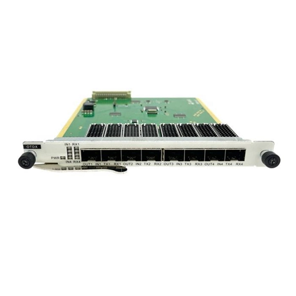
This is a simple video showing how to install a 850nm fiber optic link using SFP transceivers between 2 10 Gigabit backbone switches. Covers transceiver inst. As a leading provider of fiber optic solutions, Weunion offers a wide range of SFP-compatible products, including optical transceivers, DAC/AOC cables, LC patch cords, and MPO/MTP assemblies. This guide explores the essentials of SFP connectivity, installation best practices, and how Weunion's. These transceiver modules are hot-swappable input/output (I/O) devices that plug into 100BASE, 1000BASE and 10GBASE ports (for SFP+), which connect the module port with the fiber-optic or copper network. This document contains these sections: The SFP transceiver modules are hot-pluggable I/O. An optical module is an optoelectronic conversion device that transmits data by converting electrical signals into optical signals. Common types of optical modules include SFP, SFP+, SFP28, QSFP, QSFP28, etc. Different types of optical modules have different performance parameters such as speed. The 1310 nm WWDM solution, 10GBASE-LX4, requires the use of a mode-conditioning patch cord on multimode fiber to achieve its specified range of operating distances. more Audio tracks for some languages were automatically generated. Learn more This is a simple. One of the most widely deployed optical solutions for short-distance 10G links is the multimode SFP+ transceiver, commonly referred to as a 10GBASE-SR module.
[PDF]

Fiber optic cables offer superior performance compared to copper cables, especially over long distances. They provide higher data transmission rates, larger bandwidths and are immune to electromagnetic interference. Fiber optic cables and copper wires are the two primary types of cables used in networks. Fiber optic cables transmit data using light waves, enabling higher. Fiber optic tends to be the more premium solution, while copper wiring is far more common, but why is that? What are the differences between these two cable types, and why might you want to pick one over the other? Here's everything you need to know about fiber vs. Copper wire is more susceptible to interference and has limited data capacity, making optical fiber the preferred choice for modern high-speed. If you're deciding between copper and fiber optic cables, it's not just a question of cost, it's about purpose, environment, and future readiness. Both have distinct strengths that can serve very different networking needs depending on your setup. Fiber optic cables provide. In today's fast-paced digital world, choosing the right network cable can significantly impact the performance, reliability, and security of your communications infrastructure. Among the most commonly used cables are copper and fiber optic cables, each offering unique advantages depending on the.
[PDF]

This video shows real on-site footage of electrical installation, demonstrating safe and standardized wiring methods used by professionals. Whether you are setting up a new telephone line or troubleshooting an existing one, understanding the basics of wiring is essential. In this article, we will explore the key components of a telephone line box and the. In this video, we'll walk you through the process of wiring a home distribution box with a detailed connection diagram. What is Distribution Board? Distribution board. mounted in OnQ Service Center Enclosures and come in several different telecom/video combinations; an example (6+8) is shown yle fittings for connecting incoming and outgoing cables. ve an 8 position 110 punch-down connector for incoming 4 ine service and 110 (8) position punch-down connectors. With the right wiring diagram, you can easily complete the job and get your outside phone box up and running in no time. If you're looking for a wiring diagram to help you install an outside phone box, then you've come to the right place. From there, the wiring is divided into separate lines for different areas of the house, such as bedrooms, living rooms, and kitchens. Each line is then connected to a.
[PDF]