
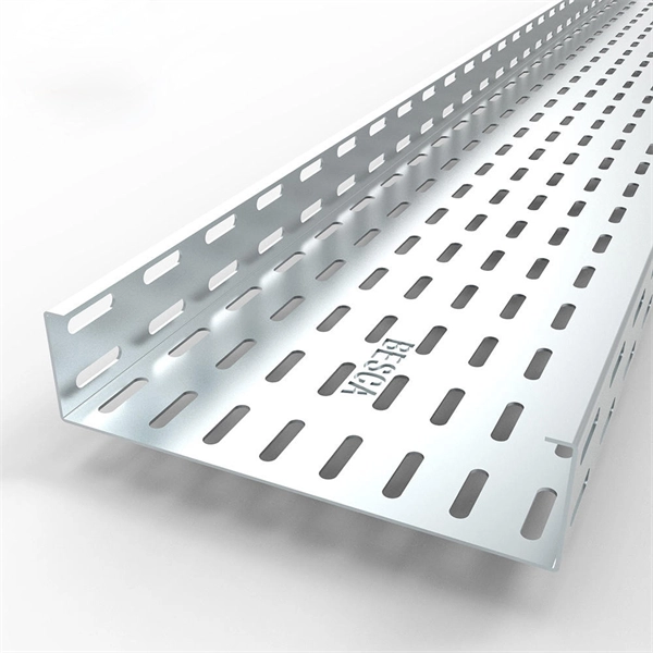
This section provides an overview for wire mesh trays as well as their applications and principles. Here are the top-ranked wire mesh tray companies as of May, 2026: 1. Code Electric Products Ltd. Attaches wire mesh tray to strut without bolts and nuts or tools. Hot dipped Galvanized Finish for exterior use Universal Dropout Kit- side mount 12" cable dropout in electrozinc. 12" Center Hanger - Only one threaded rod is needed to suspend tray. Suspension tube protects cables. Other products such as frames, handles, guides, cable rings, shelves, baskets, racks, cable management panels, container holders, shelf dividers & sterilizer carts are available. is estimated to have 10-49 employees. How can we improve? Choose from our selection of wire mesh trays, including over 475 products in a wide range of styles and sizes. Same and Next Day Delivery. Marlin Steel's wire mesh cable trays are designed for high-performance cable management in data centers, industrial manufacturing, power distribution systems, and commercial infrastructure projects. Engineered for durability and airflow, our systems provide a robust, flexible, and easy-to-install. North American cable tray systems have strict standards. These focus on durability, safety, and easy installation. Choosing a supplier that follows these standards ensures your cable management system meets high quality. It also provides long-term performance and safe operation. This guide will.
[PDF]

Since the earliest days of fiber optics, multimode cables have typically been color‑coded orange, black, or gray, while single‑mode cables are marked in yellow. For example, cable jacket color typically defines the fiber type, and can differ based on mode and performance level. These colors are typically chosen by industry standards bodies. However, there are some non-standardized colors and inconsistencies that you should be aware of. However, with the introduction of metallic connectors like FC and ST—whose bodies are difficult to color‑code—colored strain relief boots. Multimode fiber (MMF) is a kind of optical fiber mostly used in communication over short distances, for example, inside a building or for the campus. Multimode fiber optic cable has a larger core, typically 50 or 62. 5 microns that enables multiple light modes to be propagated. Because of this, more. Originally developed by the Electronic Industries Alliance (EIA) and the Telecommunications Industry Association (TIA), the TIA-598-D standard (formerly EIA/TIA-598) remains the most recognized color-coding system for optical fibers worldwide. On the right, the yellow patchcord indicates singlemode fiber and the blue connector means it is a regular PC polished connector, If it were an APC connector, it would be green. Perhaps nothing is.
[PDF]

A double switch box allows you to control two separate electrical circuits or devices from a single location. This can be useful in situations where you want to control different lights or appliances independently. Here is a step-by-step guide on how to wire a double switch box:. Connecting two electrical boxes together is a relatively simple job, but there are some important steps that must be taken to ensure it's done safely and correctly. From adding junction boxes to selecting the right wire gauge, the following steps will help guide you in installing an electrical. A double switch box, often called a double gang box, is a rectangular enclosure designed to house two electrical devices, such as two single-pole light switches. Before beginning any electrical work, safety is the. We're diving into some essential 'electrical wiring' in this video, focusing on how to properly set up an wireing a'electrical box' with a three way and single pole light switch. more Audio tracks for some languages were automatically generated. Learn more Unbelievable Trick to. This page contains wiring diagrams for two outlets in one box. Included are arrangements for 2 receptacles in one box, a switch and receptacle outlet in the same box, and 2 switches in the same box. Whether you want to control two lights from one location or two separate devices from the same switch, a double switch box is a versatile solution.
[PDF]

In today's video, we'll be unboxing the 9-Port Power Supply Box and demonstrating how to connect the cables to provide power to CCTV cameras. A CCTV power supply box sends power to all your cameras from one place. It helps keep things neat and makes your system easier to manage. In this guide, you'll learn how to install it step by step, choose the right type, avoid common problems, and keep your system running safely. Power supply boxes for CCTV are typically used in multi-camera installations instead of using single power adapters for each camera. The process is almost exactly the same if you. Installers of surveillance systems may simply control the power to various CCTV cameras using a CCTV power supply box, also known as a power distribution box (usually at the location of the DVR). This enables a cleaner camera installation. Surge protection can be accomplished in two ways. The power supply box is specifically used to transfer power requirements for all cameras plugged in on the system, to work. Security cameras use RG59U coax siamese wire or CAT5e networking cable to transmit video. Whether you are installing a power box for a new or existing camera system, it is important to understand how to connect cameras to a CCTV Power Supply Box. DC current is polarized meaning it has two leads, a.
[PDF]

This is a simple video showing how to install a 850nm fiber optic link using SFP transceivers between 2 10 Gigabit backbone switches. Covers transceiver inst. As a leading provider of fiber optic solutions, Weunion offers a wide range of SFP-compatible products, including optical transceivers, DAC/AOC cables, LC patch cords, and MPO/MTP assemblies. This guide explores the essentials of SFP connectivity, installation best practices, and how Weunion's. These transceiver modules are hot-swappable input/output (I/O) devices that plug into 100BASE, 1000BASE and 10GBASE ports (for SFP+), which connect the module port with the fiber-optic or copper network. This document contains these sections: The SFP transceiver modules are hot-pluggable I/O. An optical module is an optoelectronic conversion device that transmits data by converting electrical signals into optical signals. Common types of optical modules include SFP, SFP+, SFP28, QSFP, QSFP28, etc. Different types of optical modules have different performance parameters such as speed. The 1310 nm WWDM solution, 10GBASE-LX4, requires the use of a mode-conditioning patch cord on multimode fiber to achieve its specified range of operating distances. more Audio tracks for some languages were automatically generated. Learn more This is a simple. One of the most widely deployed optical solutions for short-distance 10G links is the multimode SFP+ transceiver, commonly referred to as a 10GBASE-SR module.
[PDF]

Step-by-step guide on connecting an inverter to your distribution board for uninterrupted power supply. The process begins with turning off the main power supply to ensure safety. Next, choose an inverter with a suitable capacity to handle your power needs, ensuring it matches the. In this article, you will find information about connecting inverter to distribution box: essential safety tips, step-by-step guidance, and common mistakes that often lead to inverter failure, so that you can avoid them. Last Updated on September 17, 2025 by June The most extensive use of inverter. Connecting an inverter to a distribution board allows you to harness stored energy from batteries or solar panels for powering electrical devices in your home. This setup provides backup power during outages and can also contribute to energy savings by utilizing renewable energy sources. This guide. In this video, we'll guide you through the process of wiring a UPS (Uninterruptible Power Supply) or inverter for your home or office. By following a few simple steps, you can easily learn how to connect an inverter DB wiring diagram. Connecting an inverter DB wiring. Scroll to the bottom of any page to find a sun or moon icon to turn dark mode on or off! I'm not an electrician and do not want to screw this up. What type of wiring do I need to connect the inverter to the distribution box? I have a 1*60A 4*20A FL+LS distribution box with a Sungold Power 5000W 48V.
[PDF]

It is relatively affordable, especially when considering its durability and long lifespan. Additionally, it requires minimal maintenance, reducing ongoing costs. It is generally easy to install and can be quickly integrated into different systems or structures. Wire Mesh Cable Tray is often a cost-effective solution compared to other materials. We produce cable trays & their accessories, twists, elbows, tees, cross, reducers, etc. Our trays are designed to remain flexible offering organized solutions that helps minimize problems with full focus on safety in Bhutan. Strong Support: It holds heavy cables securely. Neat Organization: Keeps wiring systems tidy and safe. Explore and shop for the finest Wire Mesh Cable Tray online at India's leading marketplace for construction materials, industrial tools, electricals, and office equipment. brings the Cable Trays in Bhutan just for you! We, one of the well-known Cable Trays Manufacturers in Bhutan, offer top-notch trays that keep your electrical system organized and protected. Our range is customized and passes stringent quality tests, before reaching the market.
[PDF]

In this tutorial, I will show you how you can connect the Optocoupler to Arduino, read the data as Analog or Digital, and if necessary convert the analog values to digital, and how to reduce noise from the sensor. The Infrared Slotted Optical Optocoupler Module is a device that uses infrared light to transmit signals between two electrically isolated circuits. It consists of an infrared emitter (LED) and a photodetector (phototransistor) housed in a slotted enclosure. When an object passes through the slot. Slotted Optocouplers (Photo Interrupters) are very useful sensors, often included in Arduino projects to detect position of moving objects, measure speed of rotation, or linear motion, frequency of events, and many others. They are easy to use, but it is important to understand how they work, so. This tutorial is a comprehensive, practical guide to the Speed Sensor / Tacho Sensor (Slot-Type Optocoupler) (Leobot Product #245). Moreover, a simple application is programmed that shows how to wire and how to program an Arduino when working with the module. In this tutorial, the module is used as an “digital input board”. If you want to use the. In this project, I will talk about Phototransistor Optical Interrupter Switches (Opto Coupler) Module, how this module works and helps in determining the speed of a rotating object and finally I will show you how to Interface Optical Interrupter Switch Sensor with Arduino and measure the speed of a.
[PDF]
We cover everything from separating color-coded wires and securing them with ties to installing MCBs, main breakers, and a changeover switch for hassle-free control over your home's power supply. Right-click an app's icon to pin it or drag the app icon to the taskbar. Personalize the taskbar by removing the search box, hiding system icons, moving the. Learn how to professionally wire and organize an electrical distribution board in this step-by-step guide designed for DIY enthusiasts, electricians, and anyone looking to ensure a neat, safe installation. The coating shall be firmly attached and uniform in color, without falling, class barge, missing spraying and other adverse phenomena. There shall be no significant color difference and reflection at. Hey, in this article we are going to see the Single Phase Distribution Box Wiring Diagram and Connection Procedure. A distribution board or distribution box is where the main power supply is distributed to multiple loads. Covers wiring, placement, standards, and expert tips for a compliant setup. It takes the incoming power and safely distributes it to different circuits throughout your building.
[PDF]

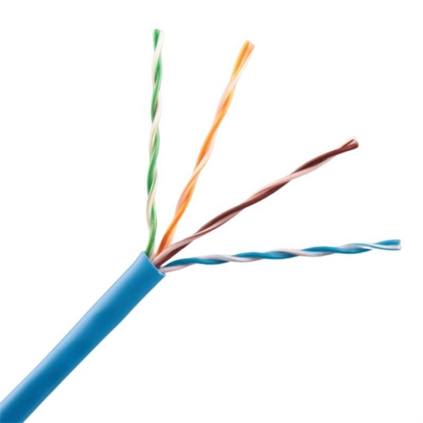
Fiber optic cables offer superior performance compared to copper cables, especially over long distances. They provide higher data transmission rates, larger bandwidths and are immune to electromagnetic interference. Fiber optic cables and copper wires are the two primary types of cables used in networks. Fiber optic cables transmit data using light waves, enabling higher. Fiber optic tends to be the more premium solution, while copper wiring is far more common, but why is that? What are the differences between these two cable types, and why might you want to pick one over the other? Here's everything you need to know about fiber vs. Copper wire is more susceptible to interference and has limited data capacity, making optical fiber the preferred choice for modern high-speed. If you're deciding between copper and fiber optic cables, it's not just a question of cost, it's about purpose, environment, and future readiness. Both have distinct strengths that can serve very different networking needs depending on your setup. Fiber optic cables provide. In today's fast-paced digital world, choosing the right network cable can significantly impact the performance, reliability, and security of your communications infrastructure. Among the most commonly used cables are copper and fiber optic cables, each offering unique advantages depending on the.
[PDF]

When you look at a fiber optic cable, the outer jacket color instantly tells you what type of fiber is inside. This color-coding system is standardized under TIA-598-C, making it easier for technicians and installers to identify cables at a glance. By adopting the TIA/EIA‑598C standard, you gain a universal “language” of colors that speeds identification, reduces miswiring, and enhances safety across cable jackets, connectors, buffer tubes, and splice trays. Error Reduction: A standardized palette prevents costly mis‑splices and. In fiber communications, the color of the fiber is not only an eyes-only indicator—it is actually used for determining the quantity, type of the fiber, and use of the fiber. Every fiber is color-coded, and this is a very crucial detail in the installation process, maintenance procedure, and. The fiber optic color codes refer to a standardized system used to identify individual fibers within a particular cable. These codes ensure correct organization and connectivity during installation or maintenance processes. The colors typically follow a color scheme established by industry. To solve this, the industry relies on an authoritative color-coding system: the EIA/TIA-598 Standard, which provides unified guidelines for identifying optical fibers, cable jackets, buffer tubes, and connectors.
[PDF]

This video shows real on-site footage of electrical installation, demonstrating safe and standardized wiring methods used by professionals. more Learn how to wire a distribution box step by step! This video shows real on-site footage of. Connecting a distribution box involves several steps to ensure proper electrical flow. Follow this guide for a clear and safe connection process: Before starting, always ensure the main power is turned off to avoid electrical shock. Fix the box securely to the wall, ensuring it's at an accessible. An electrical panel box, also known as a breaker box or a distribution board, is a crucial component of any electrical system. It serves as a central hub for distributing electricity throughout a building, ensuring that power is delivered safely and efficiently to all the required locations. In this guide, we'll break down everything you need to know to install a distribution box correctly and confidently. Choose the right box based on environment (indoor/outdoor), load capacity, and durability. Check for proper IP/NEMA ratings and material quality. Whether you're an electrician or a DIY enthusiast, this guide will help you understand the basics of home electrical distribution. Material preparation: Prepare the required circuit breakers, wires, wiring ties and other materials, and ensure that they meet the design drawings and installation requirements. Location determination:.
[PDF]

Learn how to safely wire a single-pole (one way) light switch in this beginner-friendly tutorial. Whether you're replacing an old switch or doing your first DIY electrical project, this guide will walk you through every step — no experience needed!. more. This page contains wiring diagrams for household light switches and includes: a switch loop, single-pole switches, light dimmer, and a few choices for wiring an outlet/switch combo device. That's because virtually all light switches that control 120-volt fixtures are single-pole switches. Most light switches are also single-throw, which. Summary: Fully explained wiring diagrams and photos show how to wire switches including: single switches, 3-way switches, 4-way switches, and dimmer switches. and Be Sure to Subscribe! Make sure the circuit power has been turned off, and mark the circuit breaker or fuse to indicate that work is. A distribution board or distribution box is where the main power supply is distributed to multiple loads. And all the switching and protective devices are installed in the distribution box. Single Phase Distribution Box generally consists of Double Pole MCBs, Single Pole MCBs, and RCCBs. Wiring a single light switch may seem like a daunting task, but with the right tools, a bit of patience, and this comprehensive guide, you'll be able to tackle this DIY project with confidence. Remember, while this guide provides detailed instructions, always prioritize safety and consult a.
[PDF]
Learn how to install a distribution box safely and correctly. Covers wiring, placement, standards, and expert tips for a compliant setup. It takes the incoming power and safely distributes it to different. In this video, we'll walk you through the process of wiring a home distribution box with a detailed connection diagram. more Welcome to our channel! In this video. Single Phase wiring installation is the most common wiring in residential buildings. In Single Phase supply (230V in UK, EU and 120V & 240V in the US & Canada), there are two (one is Line (aka Phase, Hot or Live) and the other one is Neutral) incoming cables from the utility poles to the kWh energy. The electrical service panel, often called a breaker box, acts as the central distribution point for all electricity entering a home. An electrical panel box, also known as a breaker box or a distribution board, is a crucial component of any electrical system. It serves as a central hub for distributing electricity throughout a building, ensuring that power is delivered safely and efficiently to all the required locations. And all the switching and protective devices are installed in the distribution box. Single Phase Distribution Box generally consists of Double Pole MCBs, Single Pole MCBs, and RCCBs.
[PDF]

Use your pliers to twist the pigtail wire and the ground wire together. Snip the sharp edge at the terminal and then insert it into the wire cap. If your metal box is in use, secure a green screw in the threaded opening at the back of the metal box. In this guide, I will teach you how to pigtail ground connections in metal and electrical boxes, and how to make a perfect pigtail. Below I will provide straightforward. Pigtailing is an essential electrical wiring technique used when adding devices or when there aren't enough spaces in a junction box. 📌 What You'll Learn in. If you have a pigtail for three wires (say # 14 AWG if that makes a difference) together in a wire nut but you want to add another wire to the mix. Is the proper method to undo the wire nut and untwist them and try to straighten out all three as best as possible? (In IT there was a tool to. Before diving into the mechanics of twisting, it's crucial to understand the two primary components involved: the wire itself and the pliers you'll be using. The success and durability of your twist depend heavily on selecting the appropriate materials and tools for the job. This technique is often employed when three or more wires need to be joined, ensuring that the. A pigtail wire is a short cable used to lengthen short wires. Also, it can join several wires to become a single conductor for electrical connections. The National Electrical.
[PDF]