Ensure safe placement: install in dry, accessible areas with good ventilation and at appropriate height (typically ~1. Practice good wiring: secure grounding, neat cable management, proper insulation, and correct wire gauge and breaker size. The term “four wires” refers to three live wires and one neutral wire, designated as A|B|C|N|, with N representing the ground wire. The three live wires should be connected to the upper entry of the main switch in the explosion-proof distribution box, and the neutral wire should be directly. Learn how to wire a distribution box step by step! This video shows real on-site footage of electrical installation, demonstrating safe and standardized wiring methods used by professionals. This ensures compliance with NEC and simplifies troubleshooting. Include protection devices like breakers, fuses, and. Prevention of Electrical Hazards: Proper wiring ensures that electrical currents flow smoothly and safely through the circuits, minimizing the risk of electrocution and electrical accidents. Faulty wiring can result in electric shocks and even be life-threatening. Efficient Power Distribution: The. ormal operation due to poor manufacture quality. A paid repair will be provided if the warranty period expires. For any damage due to one of the following situations, a paid repair duct, please dispose the pro ype, a “R” is added after the Specification. For single row 20, and circuit 24, fter.
[PDF]

Whether you're an electrician or a DIY enthusiast, this tutorial will help you understand the fundamentals of wiring a distribution box for a residential setup. The diagram of the distribution board's wiring shows exactly how each circuit is wired and connected. What is Distribution Board? Distribution board. A distribution box is the heart of any electrical system. It takes the incoming power and safely distributes it to different circuits throughout your building. Whether in a home or an industrial facility, this box keeps your electrical setup organized, functional, and efficient. However, the key to. In this guide, we will break down the key elements involved in connecting the main power supply to your home, providing a clear path for a successful setup. We will focus on the critical parts of the system, from basic components to step-by-step assembly procedures. It serves as a central hub for distributing electricity throughout a building, ensuring that power is delivered safely and efficiently to all the required locations.
[PDF]

In the following tutorial, we will show how to wire 120V single-phase and 240V split-phase circuit breakers and loads inside a residential main panel. The figure below shows a typical breaker panel used for 120V and 240V circuits. Messy distribution boxes are dangerous and very hard to fix. You will learn to build a safe, efficient, and professional electrical system today. Circuit breaker wiring configurations involve organizing main switches, busbars. A breaker box, also known as a circuit breaker panel, is an essential component of any electrical system. It is responsible for distributing electricity throughout a building, ensuring that each circuit receives the proper amount of power. To understand how a breaker box works, it is helpful to. Each circuit is protected by a circuit breaker, a safety device that automatically shuts off power if it detects an overload or a fault. If you're looking to replace an old fuse box replacement or upgrade your home's power capacity, you'll be dealing with the load center or service panel. The distinction between 1P and 2P circuit breakers plays a pivotal role in determining the appropriate protection level for various circuits. When installing or troubleshooting a power distribution system, understanding how to correctly connect the main electrical supply to the control panel is crucial.
[PDF]

This installation note provides the installation instructions for the Cisco small form-factor pluggable (SFP) and SFP+ transceiver modules. This document is intended to serve as a guide for architecting and deploying fiber optic networks in a customer environment. These transceiver modules are hot-swappable input/output (I/O) devices that plug into 100BASE, 1000BASE and 10GBASE ports (for SFP+), which connect the module. This manual provides safety and installation instructions for the 9490-OS Fiber Optic Passive Splitters. All units use type LC connectors and vary only in the splitting fan-out, and as single or dual-channel capability as listed below. Optical fibers require special care during installation to ensure reliable operation. Installation guidelines regarding minimum bend. Listings and approvals under Time Recorder Co. are the property of Tyco Fire Protection Products. Description Multiple Signal Fiber Optic Modems combine multiple system communications signals and convert them to fiber optic communications for transmission. This guide will focus on the 1x9 dual SC optical transceiver products. Pin Assignment & Description TD+, TD: DC coupled LVPECL inputs for the transmitter.
[PDF]

This guide shows you how to organize circuit breaker wiring properly. You will learn to build a safe, efficient, and professional electrical system today. Circuit breaker wiring configurations involve organizing main switches, busbars, and branch breakers within a distribution box. Messy distribution boxes are dangerous and very hard to fix. It takes the incoming power and safely distributes it to different circuits throughout your building. Whether in a home or an industrial facility, this box keeps your electrical setup organized, functional, and efficient. The distinction between 1P and 2P circuit breakers plays a pivotal role in determining the appropriate protection level for various circuits. Learn how to wire a distribution box step by step! This video shows real on-site footage of electrical installation, demonstrating safe and standardized wiring methods used by professionals. It serves as a central hub for distributing electricity throughout a building, ensuring that power is delivered safely and efficiently to all the required locations. At the heart of a breaker box is the main breaker, which controls the flow of electricity from the utility into the building. From the main breaker, power is sent to individual circuit breakers, each of.
[PDF]
The 11-in-1 Screwdriver includes the 8 bits and 3 nut drivers most requested by professionals. The bit prevents bit wear from hardened screws and extends bit life when fastening specialty screws found in elec.
[PDF]
Free electrical calculators for wire sizing, voltage drop, load calculations, conduit fill & power factor. NEC compliant tools for electricians & engineers. In this guide, we'll break down everything you need to know to install a distribution box correctly and confidently. Choose the right box based on environment (indoor/outdoor), load capacity, and durability. Check for proper IP/NEMA ratings and material quality. Ensure safe placement: install in. Professional electrical wire sizing tool based on National Electrical Code (NEC) standards. Calculate proper wire gauge, voltage drop, and ampacity for safe electrical installations. Input your electrical parameters to get accurate wire size. Pro Insight: A well-planned distribution box feels like a silent partner—you only notice it when something's wrong. Our goal? Make sure you never notice it. Before we dive into calculations, let's get familiar with a few essentials: 1. Create accurate bids and win more projects with automated formulas. The sizing requirements for pull boxes, junction boxes, handhole enclosures, and conduit bodies exist to prevent conductor insulation damage. Those requirements are in 314. 28, and they apply to all conductors 4 AWG and larger (Fig. To illustrate how these requirements prevent conductor. Estimate wire ampacity with derating factors for temperature and conduit fill. Reference tool based on NEC guidelines. It is NOT a substitute for professional.
[PDF]

The complete process for terminating cable runs at a patch panel, from mounting and cable management to punch-down, labeling, and testing every port. To wire a patch panel: Mount the panel in your rack. If you're still deciding which panel style fits your site (keystone vs punch‑down vs pass‑through), start with How to choose a patch panel and come back here once the hardware is locked in. 60-second answer If you want reliable results, the winning recipe is simple: keep pair twists tight right up. Network patch panel, cable manager, network cable, wire stripper, crimping tool, zip ties. Use a small yellow tool or wire stripper to remove the outer jacket of the network cable. Cut off the cross-shaped skeleton of the Cat6 patch cord. Insert. Patch panels make cable management and network organization very easy over long periods of time, but you'll need to wire the panels in order to put them into your network. Not to worry, this guide will walk you through the whole process. Before you jump into the task, ensure that you have the. Testing a patch panel is an essential task to ensure the reliability and efficiency of a network infrastructure. The process verifies the end-to-end connection, ensuring the cable is properly terminated at the wall jack and at the distribution point, such as a switch or patch panel.
[PDF]

This publication shows how to wire and install the 4010-9825 24V Distribution Block into a 4010 Fire Alarm Control Panel (FACP). Refer to the 842-058 Field Wiring Diagram for additional wiring information. 1 Transformer connection: Two red wires connect to AC 220V input port, while two yellow wires connect to AC input port of main board (had connected by the factory. 2 DC12V battery connection: Red wire on the circuit main board connects to the positive pole of acid-lead battery while black. Notify the carrier and call Telect's Customer Service Department at 1-800-551-4567. Keep the container until you have checked equipment operation. Use the original, undamaged container if you are instructed to return. Learn how to wire a distribution box step by step! This video shows real on-site footage of electrical installation, demonstrating safe and standardized wiring methods used by professionals. Such a system, however, does not assure. Material preparation: Prepare the required circuit breakers, wires, wiring ties and other materials, and ensure that they meet the design drawings and installation requirements. Location determination: Determine the installation position of the circuit breaker according to the position of the.
[PDF]

We will look at how to interpret PLC LED status indicators for digital inputs and outputs and how to perform troubleshooting tests using a Digital Multimeter. This section includes the block diagram of the DI 16x24VDC ST module with the terminal assignments for a 1-wire connection. Information on wiring the BaseUnit can be found in the system manual ET 200SP distributed I/O system. The load group of the module must begin with a light-colored BaseUnit. How to wire real-world signals into the Logo's digital inputs to detect whether a machine is running. Covers stack lights, door sensors, relay contacts, and proximity switches — with a complete wire diagram and step-by-step instructions for both electrical engineers and IT teams. You have a Siemens. PLC and DCS control systems Wiring Diagrams for Digital Input (DI), Digital Output (DO), Analog Input (AI), and Analog Output (AO) signals. be responsible or liable for indirect or consequential damages resulting from the use or application of this equipment. The examples and diagrams in this manual are included solely for illustrative purposes. Because of the many variables and requirements. This manual contains information that is necessary to use the NX-series Digital I/O Unit. PLC programs rarely cause failures, so in this article, we'll assume that there are no program errors and that the fault originates in the.
[PDF]

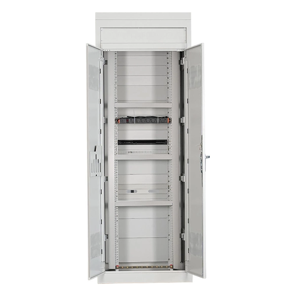
Wiring an electrical panel box can seem like a daunting task, but with the right knowledge and tools, it can be done successfully. In this guide, we will provide you with a step-by-step process to help you wire an electrical panel box safely and efficiently. Distribution Board or DB is an electricity supply system or a common enclosure that distributes the electrical power feed into subcircuits. It includes isolator, RCCB (Residual current circuit breaker) or RCD (Residual-current device) devices, protective fuses or MCB's (Miniature Circuit Breaker). This book serves as a concise guide for learners interested in basic electrical house wiring concepts. It provides practical instructions for various electrical configurations and connections, emphasizing the importance of safety and proper installation. Additionally, it introduces essential. The Guidelines For Electrical Wiring In Residential Buildings has been prepared as a wiring guide for all Wiremen and Electrical Contractors for undertaking electrical wiring in residential buildings to conform to the Electricity Regulations 1994. The Guidelines are prepared in a concise and. An electrical panel box, also known as a breaker box or a distribution board, is a crucial component of any electrical system. All the electrical sub circuits are originated from a Distribution Board. To understand how a breaker box works, it is helpful to.
[PDF]
A low-voltage wiring system in buildings may be used to operate line-voltage lights, receptacles, motors, or other devices. This system is made up of low-voltage switches that operate relays that actuall.
[PDF]

This is the FOA's Online Guide To Fiber Optics, Fiber Broadband & Premises Cabling. With 19+ years of experience installing fiber-optic cables at over 20,000 locations, we've seen how prices vary based on cable type, project scope, and installation complexity. Fiber-optic cable materials typically cost $1 to $6 per linear foot, depending on fiber count and cable type. Main cost drivers include cable grade (indoor vs outdoor, armoured), distance, and labor for trenching, splicing, and termination. This guide presents ranges in USD and practical price estimates to help. Fiber optic cables are essential components in today's broadband, FTTx, and data center networks. Whether you're planning a national fiber rollout or sourcing cables for enterprise infrastructure, understanding how fiber optic cable pricing works can help you budget more effectively and make better. We have included Per Foot conversions for reference (1 Meter ≈ 3. Best For. * Disclaimer: Prices fluctuate based on raw material indices (Glass/Copper/Polymer) and cable core count (e. These cables, constructed with glass or plastic fibers, transmit data through light pulses, offering.
[PDF]
One key aspect of this progression is the advent and evolution of transceivers, specifically SFP, SFP+, SFP28, QSFP+, and QSFP28. Let's delve into each of these technologies to understand their specifications, differences, and applications. A Cisco compatible SFP list 2026 represents a validated inventory of optical transceivers that utilize Multi-Source Agreement (MSA) standards to provide identical functionality to Cisco Original Brand (OB) optics. Deploying these modules allows network architects to reclaim up to 80% of their. —— Explosive Growth of 800G/1. 6T Technologies, Scene-Based Selection + Finisar Original Solutions in One Stop In 2026, driven by AI computing power, optical modules have entered a critical era of rate iteration, technological restructuring, and scenario segmentation. 800G has become the mainstream. Choosing the right Small Form-factor Pluggable (SFP) transceiver is critical for network engineers and procurement specialists aiming to optimize performance, cost, and reliability. This SFP buying guide offers a detailed technical comparison, real-world deployment insights, and practical selection. ity with compelling economics. Our ONE Network platform simplifies management of Cambium Networks' wired and wireless broadband and network edge technologies. Our customers can f iness rather than the network. We mak. SFP+ 10G ZR is designed for stable 80km single-mode transmission where standard 10G optics fail.
[PDF]

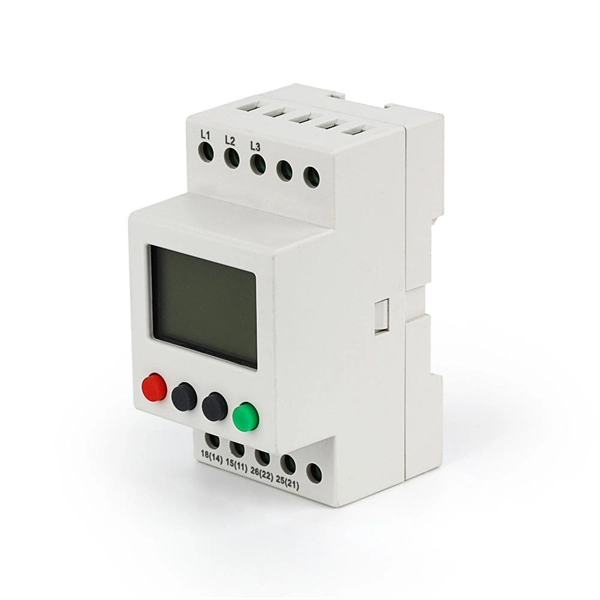
There are many types of protective relays, and each one is designed for a specific type of protection. Common types include overcurrent relay, differential relay, distance relay, earth fault relay, and under/over voltage relay. Protective Relay Definition: A protective relay is an automatic device that senses abnormal conditions in electrical circuits and triggers actions to isolate faults. HT panel protection relay. The HT power supply is received from GO switch and distributed to the. Provides protection, logic, and metering All-in-one solution. Combines protection, sensors, control power, and circuit breaker in a single package Typically added to a breaker close circuit to prevent accidental reclosure after a trip. Three fundamental components required for each circuit breaker. Its main purpose is to safeguard electrical equipment like transformers, generators, and transmission lines from damage due to. There are different types of relays available and each type is used based on the requirement. So this article discusses an overview of a protective relay or protection relay – working with applications.
[PDF]