
The SFP port is a built-in optical port of a Gigabit Ethernet switch, so it cannot be directly connected with a twisted pair or a jumper. It needs to be connected to an optical module first, and then it can be transmitted with an optical fiber patch cord. This chapter describes how to configure Gigabit Ethernet switching on the Catalyst enterprise LAN switches. Note For complete syntax and. Si ce produit est vendu au Canada, vous pouvez accéder à ce document en français canadien à https://www. com/support/download/. The RJ45 port is for copper cable. al installation guidelines and recommended procedures. To deploy this switch effectively and ensure trouble-free operation it is recommended to first read the relevant sections in this guide so rk administ tors and support personnel that install, e is based h relevant specif tions and. This command is configured in layer-2 interface configuration mode. The optical interface speed is fixed. The optical/electric port cannot support the gigabit and full-duplex at the same time. The ordinary TX port does not. The guidelines for configuring speed on QFX5100-48T switch are as follows: If the speed on the switch is set to 10-Gbps or auto, the switch advertises all the speeds. If you have configured the speed to 100 Mbps.
[PDF]
There are porcelain, high-voltage bushings on the cover connected to the primary line. Disconnecting switches or plug connectors shall be installed to permit the disconnection of all ungrounded conductors of each temporary circuit. All lamps for general illumination shall be protected from accidental contact or breakage. Metal-case sockets shall be grounded. Temporary lights shall. There are three main types of electrical switchgear: low-voltage (LV), medium-voltage (MV), and high-voltage (HV). Low-voltage switchgear is a common type of electrical switchgear used in various industries to regulate systems up to 1kV. It controls power flow and isolates electrical equipment, and it acts as a central hub. Recent studies indicate that up to 70% of electrical distribution system failures originate from. High-voltage switchgear is are essential electrical product used across power generation, transmission, distribution, conversion, and consumption. They manage switching, control, and protection functions for voltages from 3. High voltage switches are specialized devices designed to operate under elevated voltages, typically above. High Voltage Switchgear (HV/HT), often referred to as HV (High Voltage) or HT (High Tension) switchgear, is a vital part of modern power systems. You'll find it in power plants, substations.
[PDF]

Switches come in three types: those with purely Ethernet ports, those with purely optical ports, and those with a combination of both. Port types are limited to two: optical and Ethernet. Optical ports on switches typically accommodate optical modules for. The optical ports on the switch are usually paired together, with one TX sender and one RX receiver. The. Optical switching represents a fundamental technological evolution, shifting data routing from the domain of electrons to the realm of photons, or light. This transition allows data to remain in its native optical form as it travels through fiber optic networks, eliminating the need for. An all-optical Ethernet switch is a network switch whose service ports are entirely optical, meaning every interface uses fiber rather than copper. This design enables end-to-end optical signal transmission, avoiding the conversion between electrical and optical signals at the switch port level. Copper ports, also known as RJ45 ports, are the most common type of Ethernet switch ports. These ports use twisted-pair copper cables (Cat5e, Cat6, Cat6a, etc. Copper ports are widely used in local area networks (LANs) due to their cost-effectiveness and ease of installation. They can function as core, aggregation, and access devices on campus networks and connect to upstream and downstream devices.
[PDF]
The LEDs have three possible states: no light, a steady light, and a flashing light. Flashing lights may be slow, fast, or flickering. This light shows whether your ONT is getting power. Solid Green: The ONT is powered on and functioning normally. What to check: Make sure the power cable is securely plugged into both the ONT and a working wall outlet. If you're using a power strip, check. The tables in this article provide detailed information about the possible appearances of the LED lights on each device, the possible causes of each state, and what you should do. Ensure your Fiber Jack is connected to the network and the LED lights are connected and working properly before moving. System activity and status can be determined through the activity of the LEDs on the switch. A single tricolor LED for each SFP-DD indicates the port status. When the SFP-DD LED blinks white one time, it shows the status of the first port of the SFP-DD. An ONT may also be called a Service box. If you're having issues and can't get your ONT to power up, contact us. It flashes green during the initialization phase, remains solid green after successful initialization, and turns red when a system fault occurs. When the Status light is red, you can use a PC. Help Centre topics. Fibre ONT devices and how they work.
[PDF]

There are 48 bicolor LEDs (green/amber) for the first 48 SFP+ ports and 16 tricolor LEDs (green/amber/white) for the SFP-DD ports. The last set of LEDs pulse once in white before indicating the FC port status in green or amber. When it blinks white twice, it shows the status of the second port of the SFP-DD. The port status LEDs for the FC ports are arranged left and right to correspond to the upper and lower ports respectively in each pair. LEDs on the port side of the switch Table 1. LEDs on Cisco Catalyst 9500 Series Switches 1 Available only on switches with 10G ports. System LED Indicator System is not operational. System is operating normally. As a group or individually, the LEDs show information about the switch and about the ports Preventing Overload - Each port that provides PoE has a maximum power it can deliver. Three LEDs are used on each port. Ports on the Cisco Catalyst switch do not have LEDs. Not the question you're searching for? Each. Number of LEDs per port - Ports that cannot be split; for example, 1G ports must have 1 LED per port. Location - A port LED should be placed right above the.
[PDF]
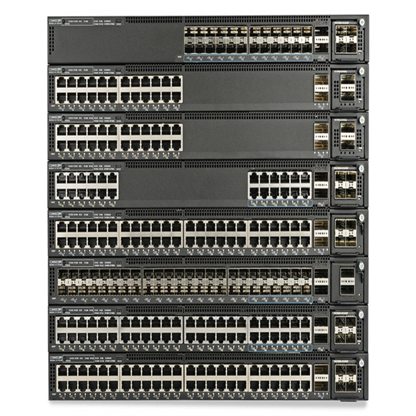
The SFP port is commonly found on Gigabit Ethernet switches and is primarily used for fiber optic device connections or for uplinking 1G switches to aggregation/core layer devices, providing higher-bandwidth links. You can add a compatible SFP transceiver module to the SFP port of. SFP ports enable Gigabit switches to connect to a variety of fiber and Ethernet cables and extend switching functionality throughout the network. Small form-factor pluggable is a hot-swappable interface used to connect network and storage switches and transfer data. Switches with SFP ports can. Choose an SFP module based on the fiber optic cabling that will be connected to the network switches. SFP transceiver modules almost always require two fiber optic cable strands. In this guide, we'll cover the following: What is an SFP port? Why is the SFP port important? SFP vs. QSFP28. Enterprise LANs use the RJ45 port on 100/1000BASE switches. It connects access layer devices and uplinks from desktop switches or directly to end devices. RJ45 ports remain essential for. An SFP switch uses Small Form-Factor Pluggable (SFP) modules to form a network switch for high-speed connectivity between devices. These interchangeable modules support various media types, including copper or fiber-optic cables, providing flexible networking options based on specific requirements.
[PDF]
F port is FastEthernet interface and fast Ethernet port, also known as 100M port. It is mainly used to connect switches or computers. When selecting or configuring a network switch, you often encounter ports labeled G, F, E, and S. Understanding the differences between these port types is essential for proper network design, cable selection, and optical module compatibility. Below, we break down each port type in detail. You can use commands to set bandwidth. This article will focus on the four common interfaces: G port, F port, E port, and S port to facilitate understanding before installation. S port The meaning of Serial interface is also called high-speed. S port is fully called serial interface, also known as high-speed asynchronous serial port. E port It is the Ethernet interface. Each Fibre Channel port can be used as a downlink (c onnected to a server) or as an uplink (connected to the data center SAN network).
[PDF]

It can be seen from the above that the aggregation switch has functions such as source address, destination address filtering, real-time policy, security, network isolation, and segmentation. Compared with access switches, aggregation switches have better performance and higher. What is an Aggregation Switch and How Does it Work? An aggregation switch consolidates data traffic from multiple network access switches into a single high-bandwidth link directed toward a core network or data center. The primary function of an aggregation switch is to aggregate and forward data. A fiber optic aggregation switch is a high-capacity network device designed to integrate and manage multiple fiber optic connections from access layer switches into fewer and faster uplink connections to the core network. It is essential for larger networks requiring efficient data flow. You may also. All-optical Ethernet switches are a type of switch that provides optical uplink and downlink ports, making them an ideal choice for building an all-optical campus network. They can function as core, aggregation, and access devices on campus networks and connect to upstream and downstream devices. As the physical entity of the aggregation layer, the aggregation switch's primary function is to aggregate the data of the access layer switch and forward it to the core switch to reduce the burden on the core layer. Cisco's aggregation switch What is the Role of the Aggregation Switch in the.
[PDF]
The WannaCry ransomware attack was a worldwide cyberattack in May 2017 by the WannaCry ransomware cryptoworm, which targeted computers running the Microsoft Windows operating system by encrypting data and demanding ransom payments in the form of bitcoin cryptocurrency. It was propagated using EternalBlue, an exploit developed by the United States National Security Agen. DescriptionWannaCry is a , which targets computers running the by encrypting (locking) data and demanding ransom payments in the. The attack began on Friday, 12 May 2017, with evidence pointing to an initial infection in Asia at 07:44 UTC. The initial infection was likely through an exposed SMB port, rather than as initially ass. Linguistic analysis of the ransom notes suggested the authors were likely fluent in Chinese and proficient in English, as the versions of the notes in those languages appeared to be human-written while the rest seeme. The ransomware campaign was unprecedented in scale according to, which estimates that around 200,000 computers were infected across 150 countries. According to, the four mo.
[PDF]
You can connect two Switch consoles via a network in two ways: Wi-Fi or Ethernet cable. For a more stable wired connection, use a Nintendo Ethernet adapter and a category 5e or higher cable. Important: A USB LAN Adapter can be connected to Nintendo Switch Lite using a licensed accessory, such as the Dual USB PlayStand for Nintendo Switch Lite from HORI. Nintendo Switch can connect online with a wireless connection or, when through use of a LAN adapter, a wired connection. Game sharing between two Switch consoles involves setting up your Nintendo. TL;DR: Is there a way to have two different (unreliable) ISPs connected to a single network switch, so that when one drops out, the home network is automatically switched to the other ISP? --- Hi all! I am a networking hobbyist, and I built out a home network for a family friend of mine living in. To view and connect your Nintendo Switch to either the 2. 4 GHz or 5 GHz Wi-Fi band, follow these steps:. 4 GHz and 5 GHz. But before we get into the details, it's essential to understand that the Nintendo Switch supports both 2. 4GHz and 5GHz WiFi frequencies, ensuring faster and more reliable connectivity. Cisco ® Catalyst ® 9200 Series switches extend the power of intent-based networking and Catalyst 9000 hardware and software innovation to a broader set of deployments. With its family pedigree, Catalyst 9200 Series switches offer simplicity without compromise – it is secure, always on, and IT.
[PDF]

How to Enable Trunking on Cisco Switch A trunk port carries many VLANs over one link between switches using 802. You turn it on with "switchport mode trunk" on the connecting interfaces at both ends. The port then adds a small VLAN ID to each frame and keeps traffic separate. A trunk is a point-to-point link between one or more Ethernet switch interfaces and another networking device such as a router or a switch. Ethernet trunks carry the traffic of multiple VLANs over a single link, and you can extend the VLANs across an entire network. You can configure a trunk on a. Understanding how to configure, verify, and troubleshoot 802. 1Q trunks is essential for building scalable switched networks. No intervening, non-trunking devices are allowed. It is important to note that ports on both ends of a port trunk group must have the same mode. Configuring a trunk port on a Cisco switch is essential for enabling the transmission of multiple VLANs across a single physical link. It is an important skill in Cisco's IT infrastructure training. Trunk ports allow switches to communicate with each other by carrying traffic for multiple VLANs. On Cisco switches, configuring trunk ports involves a precise understanding of protocols, commands, and best practices. This article provides a comprehensive guide to configuring and verifying trunk ports on Cisco switches, designed for network engineers, developers, and technology enthusiasts.
[PDF]
The layer 2 switches prevent over-crowding of data packets in transmission links and access devices. · Layer Positioning: The data link layer (Layer 2) of the OSI model, realizing local forwarding of data frames based on MAC addresses. · Core Task: Establishing direct interconnections between devices within a local area network to ensure efficient communication within the same network segment. ·. The core layer is the backbone of the network. It provides a high-speed connection between different distribution layer devices. The distribution layer connects the access layer to the core layer. When designing a campus LAN, you may. In enterprise networking, the hierarchical three-tier model is divided into three distinct roles: access switches (which connect end-user devices to the network via Layer 2), distribution switches (which route inter-VLAN traffic and enforce security policies at Layer 3), and core switches (which. The core switch is the most important piece of hardware in this infrastructure, acting as the high-speed, central nervous system that ensures all parts of the network can communicate. The core switch functions as the central point of the entire network, forming the high-speed backbone for the. Distribution Layer: The distribution layer is an intermediate layer. Simply put, it's the kingpin that keeps your network humming. You may also want to know: Can a Nintendo Switch Play DS Games? ·.
[PDF]
With up to 48 10 GE downlinks and 40/100 GE uplinks, the S6730‑H series supports bandwidth-hungry access and spine layers—perfect for Wi‑Fi 6 APs, 4K/8K video, and virtualization workloads. Based on Huawei's VRP OS, the series delivers OSPF, BGP, RIPng, IS‑IS, VRRP, and. This document provides campus networks typical configuration examples and feature typical configuration examples. "Campus Networks Typical Configuration Examples" provides typical campus network networking modes and a variety of deployment examples. Positioned perfectly as an Aggregation Switch or Core Switch, the S6730‑H delivers scalability, security, and cost-effectiveness for modern digital. The S5730-SI series switches are next-generation standard gigabit Layer 3 Ethernet switches. They can be used as access or aggregation switches on a campus network or as access switches in a data center. It also provides enhanced Layer 3 features and mature IPv6 features. eKitEngine S530 switches can be use in various scenarios. The S3700 utilizes cutting-edge hardware and Huawei Versatile Routing Platform (VRP) software to provide high-performance access and aggregation to an enterprise campus network.
[PDF]

Power over Ethernet (PoE) does not work directly over fiber-optic cables because fiber-optic cables are designed to transmit data using light, and they do not conduct electricity. PoE requires copper cables (such as Cat5e, Cat6, or Cat6a) to deliver both power and data. Power over Ethernet (PoE) is a useful technology in powering remote devices, but as we see with any copper network cable, the challenge lies in the limited distances of UTP cabling. The maximum distance for Power over Ethernet (or any network data transmission) is 100 meters or 328 feet. However, selecting the right PoE switch requires careful consideration of factors such as projected organizational growth and device. In the field of network cabling and device power supply, Power over Ethernet (PoE) technology has become widely adopted due to its ability to transmit both data and power over a single Ethernet cable. In industrial environments, industrial switches are key network devices that are adapted to harsh. IP cameras that are part of a modern surveillance system are deployed using PoE technology that involves the use of copper based network cabling like CAT5e or CAT6 that has a data transmission limit of 100m (328ft). While that is adequate for installations for a home or small business, large scale. They have dual-port choices and are easy to set up. Media converters work well in many places. You do not have to worry about distance.
[PDF]

You can run the display arp command to view IP addresses and interfaces of servers directly connected to a switch. Since it is based on arp, it does only work for devices having an ip address in the network segment where you use that feature. So if not used in the management network, it may only be applied with L3 Switches. As far as I know it is not really the case. Ip device tracking can work on L2. Finding the IP address of your network switch is crucial for a variety of tasks, from configuring its settings to troubleshooting network connectivity issues. While it might seem like a technical hurdle, several straightforward methods can help you uncover this essential piece of information. This guide will go over how to find the IP address of the M4300 & M4250 and how to access the web interface of the switch. VLAN 1 of the switch is configured by default to receive DHCP. VLAN 1 is configured by. Is there a command that I can use through Putty to figure out the IP new IP address of the switch? Thank you! Edit: The switch is still isolated and is not connected to anything other than the workstation that I am using to configure it. Just hook back up to the COM port and look. Network switches are integral components of modern computer networks, facilitating efficient data transmission and connectivity among multiple devices. The INTERFACE field displays switch.
[PDF]
