
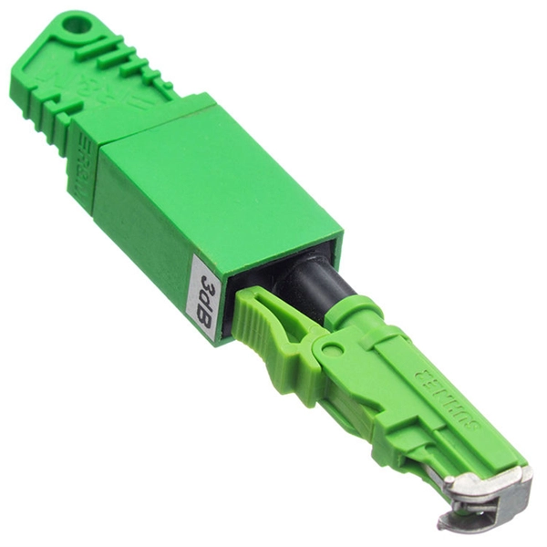
The max insertion loss of a fiber patch cable is 0. 75 dB (the maximum acceptable value) in the TIA standard. Insertion loss (IL) and return loss (RL) are key performance indicators of fiber optic patch cords. This article explains their concepts, standards, testing methods, and FiberMania's quality assurance workflow to ensure optimal network performance. Fiber optic patch cords are crucial components in. A: Fiber optic loss refers to the reduction in signal strength as it travels through the fiber optic cable. This can be due to various factors, including attenuation, connectors, and splices. Q: How is fiber optic loss measured? A: Fiber optic loss is typically measured using an Optical Loss Test. The estimate, called a "loss budget" is calculated using typical component losses for each part of the cable plant - the fiber, splices and/or connectors. If the measured loss exceed the calculated loss by a significant amount (remembering the inherent uncertainty in all measurements), the system. Insertion loss is usually shortened to IL, and the unit of measurement for insertion loss is dBm. ) in transmission systems. It is the power attenuation of the signal after. At TARLUZ, we specialize in manufacturing high-performance fiber optic patch cords that comply with global industry standards, ensuring optimal signal integrity and long-term stability.
[PDF]

The typical specification range of return loss of a fiber connector is -15 dB to -60 dB. Return loss is also known as reflection loss. It indicates the amount of signal reflected back to the transmitting end. Return loss refers to the power loss caused by the reflection of part of the signal back to the signal source during transmission due to the discontinuity of the transmission. Insertion loss, also known as attenuation, is the loss of optical power that occurs when light passes through a fiber optic connector. It is caused by factors such as misalignment, air gaps, and imperfections in the connector components. The lower the insertion loss, the better the performance of. Reflectance (which has also been called "back reflection" or optical return loss) of a connection is the amount of light that is reflected back up the fiber toward the source by light reflections off the interface of the polished end surface of the mated connectors and air. It is also called. Insertion Loss (IL) is the amount of optical power lost as the signal travels from one point to another in a fiber optic link, usually across connectors or splices. Formula for. In optical fiber communication, insertion loss and return loss are two important parameters to evaluate the quality of interfaces between some optical fiber components, such as optical fiber connector, fiber patch cable, pigtail fiber, etc. While it's natural to have.
[PDF]

Mass fusion splicing can fuse up to all 12 fibers in one ribbon at once. Entire ribbons can be spliced simultaneously. Standard mass-fusion color-coded pigtail kits contain a. Traditional Fusion Splice-On Connectors with pigtails provide factory-polished performance with field-termination convenience within harsh environments. com offers Less-Than-A-Truckload “LTL” option for products that cannot be shipped via parcel shipping. For products that will be shipped via LTL, you will be provided with a set of Accessorials to select from to provide Anixter with additional shipping considerations, such as. The Relevance Inspector will open in the Coveo Administration Console. SDX Pigtail Fusion Metal Splice Module pre-loaded with duplex LC adapters (Blue) and 12-fiber OS2 LC/UPC individual pigtails. Works with all SDX Enclosures. SDX 12- and 24-fiber splice modules protect and organize heat shrink fusion spliced fibers (up to 12 or 24 fibers) inside a fiber enclosure. The modular design enables faster field splicing and simple management of pigtails within the housing. The M4 Splice Cassette is designed for use with Single-Mode OS2 fiber, houses 12 fibers, and provides LC UPC Duplex ports.
[PDF]

It includes first determining the type of communication system (s) which will be carried over the network, the geographic layout (premises, campus, outside plant (OSP, etc. ), the transmission equipment required and the fiber network over which it will operate. Fiber optic network design refers to the specialized processes leading to a successful installation and operation of a fiber optic network. It also involves selecting transmission equipment. It includes detailed mapping of backbone, distribution, and drop connections for FTTH, FTTP, FTTx, and enterprise networks. Building a fiber optic network is a highly technical yet vital process that enables communities and businesses to access high-speed, reliable fiber optic internet. From the initial site survey to the final fiber to the home (FTTH) connection, every stage requires careful planning, coordination, and. Designing a fiber optic network is like planning a city's road system, it needs to be efficient, reliable, and built to handle both current and future traffic. Whether you're new.
[PDF]
Fiber optic adhesive is a type of specialized adhesive used to assemble and install fiber optic cables. These products provide superior bonding strength and excellent optical clarity. Master Bond's adhesives contain no potentially objectionable contaminants and exhibit excellent resistance to. Adhesives play a pivotal role in the assembly of fiber optic components due to their high performance on glass, metal, ceramic and most plastic substrates, excellent chemical and solvent resistance, and electrically insulating properties. As adhesives can bond dissimilar materials quickly. NTT-AT's series of adhesives for fiber array assemblies feature high moisture resistance and excellent workability for v-groove fixing or optical fiber fixing. It is used to bond the fiber optic connectors and ferrules to the fiber optic cable, ensuring a secure and stable connection. Fiber optic adhesive comes in different forms and compositions. Fiber Array (FA) is a V-Groove (V-groove) substrate that is used to install a bundle of optical fibers or an optical fiber strip on the substrate at a specified interval. Whether integrated into planar lightwave circuits (PLCs), optical switches, or high-speed transceivers, FAs play a vital role in ensuring.
[PDF]

They use a loose-tube construction, with the actual fiber optic core laid in a spiral pattern within semi-rigid tubes that allows the cable to stretch and flex without placing any tension on the glass fibers themselves. A conduit is a protective tube or channel that houses the fiber optic cables, shielding them from moisture, dust, physical stress, and other environmental factors. It also facilitates cable management and ease of maintenance. With these assemblies we mention in this article, the widest point of. OS1 single mode fiber optic cables are made with a single mode fiber core, which means that they have a very small core diameter of 9 microns. This allows the cables to transmit data over much longer distances than multimode fibers, with less signal loss and better quality. The construction of a single mode fiber cable, also called singlemode. Given your description, I would recommend a gel-filled armored cable These links may interest you: I would use standard electrical conduit from the trench to inside the building only. For the trench run itself I would drop in “Direct to Ground” rated cables for both fiber and copper (phonedata). Duplex: Consists of two fiber.
[PDF]

Cable laying services install fiber optic cable or copper cable in buildings and office complexes, or over large distances. They are staffed by cable technicians who perform cable preparation, jointing, termination, testing, commissioning, maintenance, and troubleshooting tasks. Installing fiber optic cables underground involves far more than digging trenches and placing cables. It forms a critical backbone for modern communication networks across both urban and rural environments. Project success depends on careful planning, precise installation practices, and proper. Installing underground fiber optic cables is critical to establishing high speed internet infrastructure that delivers reliable connectivity for businesses nationwide. Unlike traditional copper systems, fiber optic cables require specialized handling techniques and precise installation methods to. These skilled professionals ensure that your home or business is equipped with the latest fiber optic technology, providing blazing-fast Internet speeds and robust connections. This guide walks you through the entire process of fiber cable installation, from the initial assessment to the final. This involves burying or installing fiber-optic cables along predetermined routes. During this phase, locators identify existing utilities to prevent damage.
[PDF]
A fiber-optic sensor is a sensor that uses optical fiber either as the sensing element ("intrinsic sensors"), or as a means of relaying signals from a remote sensor to the electronics that process the signals ("extrinsic sensors"). Fibers have many uses in remote sensing. Depending on the application, fiber may be used because of its small size, or because no electrical power is needed at th. Intrinsic sensorsOptical fibers can be used as sensors to measure, , and other quantities by modifying a fiber so that the quantity to be measured modulates the,,, or transit time. Extrinsic fiber-optic sensors use an, normally a one, to transmit light from either a non-fiber optical sensor, or an electronic sensor connected to an optical transmitter. A major benefit of e. It is well-known the propagation of light in optical fiber is confined in the core of the fiber based on the total internal reflection (TIR) principle and near-zero propagation loss within the cladding, which is very important f.
[PDF]

1000BASE-SX is a gigabit Ethernet standard over fiber optic for short reach. It is used for operating on multimode fiber with a short wavelength of 770 to 860 nanometers (typically 850nm). The “SX” stands for short reach over multimode fiber. 1000BASE-SX defines a maximum length of 220 meters for. What Is An Sx Sfp Module? The Ultimate Guide To 1G Transceivers (Sx Vs Lx Vs Sr) If you are buying fiber optic transceivers for a network upgrade, the alphabet soup of acronyms can be a nightmare. You see SX, LX, SR, LR. and they all look like the same little metal box. But choosing the wrong one. A Beginner's Guide: What is 1000BASE-SX, 1000BASE-LX & 1000BASE-ZX? Gigabit Ethernet (GbE) has gained significant popularity and is widely used in enterprise network backbones. It's defined by IEEE standards 802. These standards are vital for Ethernet's physical layer and. 1000Base-SX is a type of standard for implementing Gigabit Ethernet networks. The SX in 1000BaseSX stands for short, and it indicates that this version of Gigabit Ethernet is intended for use with short-wavelength transmissions over short cable runs of fiber-optic cabling. The application's nominal symbol rate is 1. 25 GBd per lane and the supported distance varies according to the type of multimode cable used. These modules convert electrical signals from.
[PDF]

Its red laser shines through most yellow-jacketed optical fibers to help you pinpoint breaks, bends, faulty connectors, splices and other causes of signal loss. It has a reach of up to 5 km. The RPEN-210 is a necessity tool that should not be missing from any fiber plant manager or fiber optic installing technician. The Visual Fault Locator (VFL) Pen has a visible red light source centered on 650nm. Tool sends visible light over a fiber strand with a 10mW power, good enough to reach. The FLS-140 is the easiest way to identify optical fibers from end to end and locate polished connector endfaces. 5 dBm, but it couples approximately 3 dB less into a fiber. This is a Class 1 unit; the Class 1 limit is +3 dBm. The Class 1 limit (+3 dBm/2 mW) is intrinsically safe in all circumstances and is. This VFL has a fiber stub; its total emission is -1. 30 years of experience in R&D and manufacturing - Jilong JILONG launched the VFL-22M mini red light pen, pocket design, small and portable, integrated VFL/LED function, strong and stable light source, strong penetrating. A visible laser radiation source is one of the simplest devices and is designed to produce red light with a wavelength of 650 nm, which is transmitted through an optical fiber. The main purpose of this device is to locally detect various types of damage (such as breaks, bends, poor splicing, etc.
[PDF]

Setting up a fiber optic network requires specific equipment to ensure optimal performance. Key components include fiber optic cables, ONT, OLT, routers, Ethernet cables, NICs, Optical Power Meters, and Fiber Optic Splicers. In this article, we explore ten critical fiber optic components—from fiber optic cables to drop wire clamps—and their indispensable roles in building robust, future-ready networks. Fiber Optic Cable: The Lifeline of Data Transmission Fiber Optic cables are the highways of fiber optic networks. Let's break down the essential fiber optic components that make your high-speed connection possible. Inside these cables are incredibly thin strands of glass that transmit your data as pulses of light. Whether for residential or commercial use, investing in the right. Before diving into the tools used for installation and maintenance, it's vital to understand the core components that constitute a fiber optic network. These are the physical elements that carry the light signals, enabling high-speed data transmission. Each component plays a critical role, and. At the heart of any fiber internet infrastructure are the fiber-optic cables themselves. Renowned for their efficiency in carrying data over long distances, fiber optic cables transmit that.
[PDF]
Although fiber optic networks present many advantages, there are also some disadvantages to take into consideration. These include physical damage, cost considerations, structure, and the possibility of a “fiber fuse”. By the early 1990's, as the internet was becoming popular in the public realm, fiber optic cabling started to be laid around the world. There was a big push to wire the world in order to. Optical fiber is a type of medium used for data communication or data transmission with the help of light pulses. Optical fiber is a hair-thin flexible stand made up of glass. It is capable of transmitting optical signals from one point to another over long distances. These days, optical fibers are. Fiber optic transmission has become the cornerstone of high-capacity communication networks, powering residential broadband, hyperscale data centers, 5G, IoT ecosystems, and global long-haul infrastructure. Additionally, fiber optic cables are delicate and require careful handling and installation. Electromagnetic interference (EMI) is a disturbance caused by electromagnetic radiation from an. There are many advantages of using these cables over other kinds of communication cables, like the bandwidth of these cables is high, and they are less vulnerable than metal cables.
[PDF]
Fiber optic switches are devices used to control the flow of light in fiber optic networks. They are used in a wide range of applications, including telecommunications, data centers, industrial automation, and military and aerospace. This piece analyzes how these switches can make a difference today. Fiber optic switches offer numerous advantages over traditional. A fiber optic switch is an electronic device that allows multiple fiber optic cables to be connected and selectively route data between them. The switch receives data packets from one input fiber optic cable and forwards them to the appropriate output cable based on their destination addresses. It operates on the same principle as an electrical switch, but instead of using electrical signals, it uses light signals to switch data packets from one fiber optic cable to another. Fiber. A fiber optical switch, also known as a fiber channel switch or a SAN (Storage Area Network) switch, is a high-speed network transmission relay device. This technology offers significant.
[PDF]

This guide on how to fix router red light, will walk you through the common reasons behind the red light and provide step-by-step solutions to bring your router back online. A red light on your router can be a source of frustration and confusion. It often indicates that something is wrong with your internet connection or the device itself. Fortunately, diagnosing and resolving these issues doesn't have to be complicated. You might feel like you're staring into the abyss of digital darkness, wondering what went wrong. But don't despair! This guide will walk you through the most common causes of router. Experiencing a solid red broadband light on your router can be frustrating and indicates a disruption in your internet connection. Understanding the possible causes and fixes for this issue is crucial to getting your connection back on track. Here are some steps you can take. The following article will explain why the Internet is light red and what you need to do to fix it. What does it mean by Internet Light Red On Router? Our router's lights are.
[PDF]

Optical return loss is the amount of light that is reflected back to the source, this reflected light is measured at each connector and splice at each point over the entire fiber link. This is always measured in dB (decibels) and will be displayed as a negative number. The closer the number is to. The polish of a singlemode fiber endface plays a significant role in reflectance. Understand what you need before you specify. The Institute of Electrical and Building the ORL story Electronics Engineers (IEEE) recently Within a fiber-optic channel or path-released new specifications within way. Optical Return Loss (ORL) in fiber optics refers to the amount of light that is reflected back toward the source in a fiber link. ORL is usually expressed in decibels (dB) as a positive value, with. Return loss (RL) is also called reflection loss. When high-speed signals enter or exit a part of an optical fiber, such as an optical fiber connector, discontinuity and impedance mismatch may cause reflection, which is the return loss of an optical fiber. Poor ORL is commonly caused by dirty connectors, poor splices, mismatched connector types, or damaged fibers. ORL is measured using ORL meters. Home Coherent Optics Optical Return Loss (ORL) Explained Comprehensive Guide to Understanding and Managing Back-Reflections in Fiber Optic Systems What is Optical Return Loss (ORL)? Optical Return Loss (ORL) is a critical parameter in fiber optic systems that quantifies the amount of light.
[PDF]