How to connect multiple switches in a network with clear steps and tips for effective setup and configuration. Switches operate at the data link layer of the OSI model, forwarding packets of data between devices based on their MAC addresses. Switches come in various shapes and sizes, ranging. Cascading switches refers to the process of connecting multiple switches together in a series, effectively expanding the network's capacity and reach. This hierarchical connection allows for efficient and seamless communication between devices, regardless of their physical location within the. In the world of networking, Ethernet switches are integral components that provide the necessary interconnects for our devices. Sometimes, one switch is not enough to meet our needs, whether in terms of port number, specific functionalities, or both. Essentially, a LAN switch sets up a series of temporary networks that span only the two devices currently exchanging data. Depending on the configuration, connecting multiple switches can also. When one switch cannot meet the number of ports and a specific functional requirement, usually users will connect multiple Ethernet switches together, so how to connect multiple Ethernet switches together during network deployment? Three common types of connections are currently available:.
[PDF]

Quick answer: Choose a 12-port or 24-port ODF for small fiber terminations, branch locations, and light distribution needs. In real projects, the right optical distribution frame must match your current fiber count, rack space, adapter format, cable routing method, maintenance habits, and future expansion plan. Many buyers focus only on the initial number of terminations they need today. That often leads to one of two. An Optical Distribution Frame (ODF) is a metal unit that organizes fiber optic connections. It's where incoming and outgoing cables meet. Without it, cables get tangled. This article explores the types, components, applications, installation, and maintenance best practices, providing a. This complete guide explores everything you need to know about ODFs — from their structure, types, and key components, to installation best practices and modern design trends. Whether you're building a central office, data center, or FTTx distribution network, understanding the right ODF. This guide explores the various types of ODFs, their features, and ideal applications. Whether you're setting up a data center, deploying a telecom network, or managing fiber-to-the-home (FTTH) connections, understanding these types will help you select the right solution for efficient, reliable.
[PDF]

When you look at a fiber optic cable, the outer jacket color instantly tells you what type of fiber is inside. This color-coding system is standardized under TIA-598-C, making it easier for technicians and installers to identify cables at a glance. By adopting the TIA/EIA‑598C standard, you gain a universal “language” of colors that speeds identification, reduces miswiring, and enhances safety across cable jackets, connectors, buffer tubes, and splice trays. Error Reduction: A standardized palette prevents costly mis‑splices and. In fiber communications, the color of the fiber is not only an eyes-only indicator—it is actually used for determining the quantity, type of the fiber, and use of the fiber. Every fiber is color-coded, and this is a very crucial detail in the installation process, maintenance procedure, and. The fiber optic color codes refer to a standardized system used to identify individual fibers within a particular cable. These codes ensure correct organization and connectivity during installation or maintenance processes. The colors typically follow a color scheme established by industry. To solve this, the industry relies on an authoritative color-coding system: the EIA/TIA-598 Standard, which provides unified guidelines for identifying optical fibers, cable jackets, buffer tubes, and connectors.
[PDF]

The most commonly used primary distribution voltages are 11 kV, 6. Utilities may have some control over and access to the energy stored in electric vehicles attached to the grid. The voltage used for primary distribution depends upon the amount of power to be conveyed and the distance of the substation required to be fed. Due to economic considerations, primary distribution is carried out by. There are five main functions of the distribution substation: Voltage transformation: One or more transformers will always be located within the substation to step down the voltage to the primary distribution voltage level. These transformers will always be three-phase banks, or they will be three. Electric power distribution is the final stage in the delivery of electricity. Electricity is carried from the transmission system to individual consumers. These taps are typically single phase, but may also be two phases or three phases. Laterals can be directly connected to main trunks, but are more commonly protected by protective devices such as fuses. distribution voltages are between 4 and 35 kV. In this article, unless otherwise specified, voltages are given as line-to-line voltages; this follows normal industry practice, but it is sometimes a source of confusion. A voltage class is a.
[PDF]

Choosing the right fiber type, typically single-mode, enhances the performance of 1310nm modules, allowing for longer transmission distances. 1310nm lasers support various data rates, from 1Gbps to 100Gbps, providing flexibility for different network needs. In fiber-optic communication, a single-mode optical fiber, also known as fundamental- or mono-mode, is an optical fiber designed to carry only a single mode of light - the transverse mode. When selecting a module, consider factors. Single-mode fibers (also called monomode fibers) are optical fibers which are designed such that they support only a single propagation mode (LP 01) per polarization direction for a given wavelength. Higher-order modes like LP 11, LP 20 etc. then do not exist — only cladding modes, which are not. Gigabit single-mode fiber optic module Common parameters of optical modules 1. Center wavelength 1) 850nm (MM, multi-mode, low cost, but short transmission distance, usually only 500M); 2) 1310nm (SM, single mode, large loss during transmission, small dispersion, generally used for transmission. Single mode fiber (SMF) is a type of fiber optic cable that only allows one light mode to transmit at a time. Generally, single mode cable has a narrow core diameter of 8 to 10µm (micrometers), which can propagate at the wavelength of 1310nm and 1550nm. They feature low attenuation benchmarks 2 and minimal dispersion. They use OS1 or OS2 OS1 or OS2 classifications to.
[PDF]

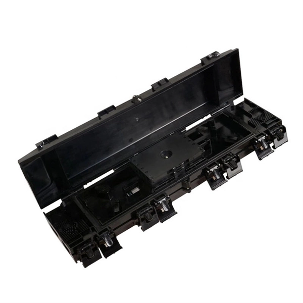
The main components of a splice box are the splice cassette that picks up the fibers and their reserves, and the front panel which contains different connectors for transmitting signals via copper or fiber optic cables. A splice box (also known as splice distributor) is a housing in which fiber optic cables begin or end. Fiber optics are fanned out in splice boxes that are situated at the end of fiber optic transmission paths. It typically consists of two parts: an outer housing and an internal structure. In this response, we will focus on the. The FSB series of indoor wall mount enclosures are designed for centralized splice-only applications. These boxes are well suited as optical cable splice collection points for DAS (Distributed Antenna Systems), MTU (Multi-Tenant Unit) commercial business applications, and MDU (Multi-Dwelling Unit). Fiber optic splice closures permanently connect two fiber optic cables together and have a splice that protects the components. The optical cable connection part, that is, the optical cable joint, is the part that protects the connection between two or more optical cables by the optical cable. Splicing refers to the permanent connection of two optical fibers to form a continuous optical connection.
[PDF]
Semiconductor laser diodes range widely in price based on a few key parameters. The wavelength, power, spectral qualities, package type, cavity type and quantity will all have an effect on the price. You can buy a laser diode for less than a dollar. Laser Diodes and Modules are semiconductor devices that can emit a beam of high intensity focused radiation, typically in the infrared, visible or ultraviolet wavelength ranges of the electromagnetic spectrum, coherently (light waves of the same wavelength, phase and direction). With power ranges. - 514nm laser diode optimized for life-science applications, housed in a TO-56 Metal Can® package. Laser Diodes are available at Mouser Electronics. Mouser offers inventory, pricing, & datasheets for Laser Diodes. But the price can also be in the tens of. Laser Diodes | UV | 375 - 400 nm Laser Diodes | VIOLET | 405 - 415 nm Laser Diodes | BLUE | 420 - 488 nm Laser Diodes | GREEN | 510 - 520 nm Laser Diodes | RED | 635 - 655 nm. Mideo Systems Inc, FOI-150 Fiber Optic Illuminator Mircoscope Light Source. WeCreat 2W IR Vision 1064nm Infrared Laser PL2302 Incomplete Missing Connection! Get the best deals on Laser Diodes when you shop the largest online selection at eBay. Free shipping on many items | Browse your favorite. This DFB laser diode (1310nm or 1550nm) has InGaAs monitor photodiode and optical isolator integrate. This 1310 nm DFB laser is a specially designed laser module for high performance analog optical tran.
[PDF]
Fiber optic cables need repeaters to boost weak signals over long distances, ensuring reliable data transmission. Signal loss occurs due to attenuation, dispersion, and physical factors like bending, which can degrade data quality. Just like your voice fades and blurs when you shout across a field, light pulses in fiber optics lose strength and clarity. Repeaters and optical. An optical communications repeater is used in a fiber-optic communications system to regenerate an optical signal. Some repeaters also correct for distortion of. Fiber Repeaters are used to extend and repeat Ethernet data signals over multimode or single mode fiber up to 160km [100 miles]. If you need to convert Single Mode to Multimode, or extend a Multimode network, Fiber Optic Repeaters are the devices to use. They are the ideal solution to connect. Model 490NRP253 provides a Fiber Optic Point-to-Point link between two Modbus Plus connections. Raman amplifiers, on the other hand, rely on the Raman effect to amplify the signals. Fiber amplifiers offer several advantages over.
[PDF]
Optical line terminals, also called optical line terminations (OLTs), serve as endpoints for passive optical networks (PONs). They convert electrical signals from equipment managed by a service provider to fiber optic signals readable by a PON. It provides two main functions: to perform conversion between the electrical signals used by the service provider's equipment and the. In the age of fiber-to-the-home (FTTH) and ultra-broadband connectivity, the Optical Line Terminal - or OLT - is one of the most crucial devices powering our high-speed digital world. When you stream a 4K video, join a remote meeting, or play an online game on a gigabit fiber connection, an OLT. At the heart of a point-to-multi-point or passive optical network (PON) is the optical line terminal (OLT). Modern OLTs offer communication service providers (CSP) the ability to launch multigigabit services to tens of thousands of subscribers from a single location or just ten. Whether you are using high-speed internet at home, watching IPTV, or running cloud-based.
[PDF]
4-Port GPON Optical Line Terminal with + 1x SFP+, Up to 2. 244 Gbps RX, Up to 512 ONUs - Total (128 Clients per Port). Rack, Wall or Desktop mount. Configuring a fiber network just became as easy as setting up a smartphone. GPON Class C+ SFP OLT Trcvr Module, 1490Tx, 1310Rx, I-Temp. TelePresence 500-37 Pedestal Bracket and Bolt Kit. 8GB DDR3-1333MHz RDIMM/PC3-10600/2x4GB 2R Kit/Low-Dual Volt. 16GB. FS provides Optical Line Terminals, free & fast delivery, expert tech support, outstanding warranties. Our silicon devices have been interoperability-tested, field-proven and adopted by various worldwide operators and carriers. designed for FTTH GPON applications. Packaged in a Small Form- infrastructure in edge, enterprise, or distributed environments. robust fiber-to-the-home (FTTH) or small-scale fiber deployments. temperature, voltage, bias current, and optical power. Say goodbye to command lines, manuals, and paid support. Economy delivery via courier or post. Orders dispatched within 24 hours on business days. Fast and secure payments via card. Bank transfers in EUR, USD or GBP. Special offers for wholesale requests. 30-day withdrawal returns. Online RMA status for warranty, replacements and repairs.
[PDF]

Non-polarizing beamsplitters are specified by their splitting ratio, i. the ratio of P-polarized light to. A beam splitter or beamsplitter is an optical device that splits a beam of light into a transmitted and a reflected beam. It is a crucial part of many optical experimental and measurement systems, such as interferometers, also finding widespread application in fibre optic telecommunications. a laser beam) into two (or sometimes more) beams, which may or may not have the same optical power (radiant flux). Different types of beam splitters exist, as described in the. The collimated incident laser beam passes through the beam splitter, and the output beam is emitted at a specific separation angle on the output beam array. The following figure is an introduction to the basic settings of a beam splitter. Circular beamsplitters, plate beamsplitters and cube beamsplitters can be purchased for polarizing or non polarizing beamsplitting. Beamsplitters are optical components used to split incident light at a designated ratio into two separate beams.
[PDF]
Metal conductors in cables serve to conduct electricity, while optical cables use optical fibers to transmit light signals, and optical fibers are thin, flexible media that transmit light beams, forming the core part of optical cables. Let's take a closer look at. Yes, there can be differences between optical cables in terms of their construction materials, connector types, and the quality of the glass fibers used. These factors can affect the cable's ability to transmit data effectively over long distances and at high speeds. It's important to choose the. Toslink—short for “Toshiba Link”—is a very specific subset of fiber‑optic technology created in 1983 to move consumer‑level digital audio from one box to another. Let's take a closer look at these differences. Cables physically connect these devices, enabling them to communicate within a network. In computer networking, it is very important to know the distinctions between the different. These cables are used mainly for digital audio connections between devices. A fiber-optic cable, also known as an optical-fiber cable, is an assembly similar to an electrical cable but containing one or more optical fibers that are used to carry light. They are mainly used in telecommunications, data transmission and consumer electronics. Compared to traditional cables that carry electrical signals, optical ones have Cables some advantages.
[PDF]

Multi-mode fiber optic patch cords utilize a larger core size, typically around 50-100 microns, allowing them to carry multiple modes of light. This design enables the transmission of data over relatively short distances with high bandwidth capabilities. A fiber-optic patch cord is a fiber-optic cable capped at each end with connectors that allow it to be rapidly and conveniently connected to telecommunication equipment. This is known as interconnect-style cabling. A fiber-optic patch cord is constructed from a core with a high refractive. These short fiber optic cords connect transceivers, switches, patch panels, and servers. Without them, even the best optical modules and switches cannot deliver performance. As data rates increase from 10G → 100G → 400G → 800G, patch cables must handle more bandwidth, more density, and stricter. Fiber optic patch cords, also known as fiber optic patch cables or fiber jumpers, are indispensable components in modern optical networks. They act as the critical link for interconnecting devices like optical switches, servers, and distribution frames. Understanding the various technical. Fiber patch cables, also called fiber-optic patch cords, are cables typically containing one or two optical fibers, which are equipped with standardized fiber connectors on both ends. The function of the fiber patch cord.
[PDF]

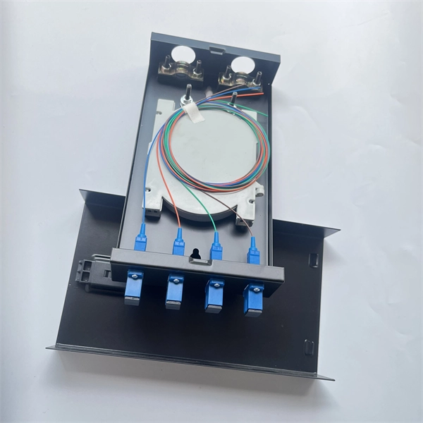
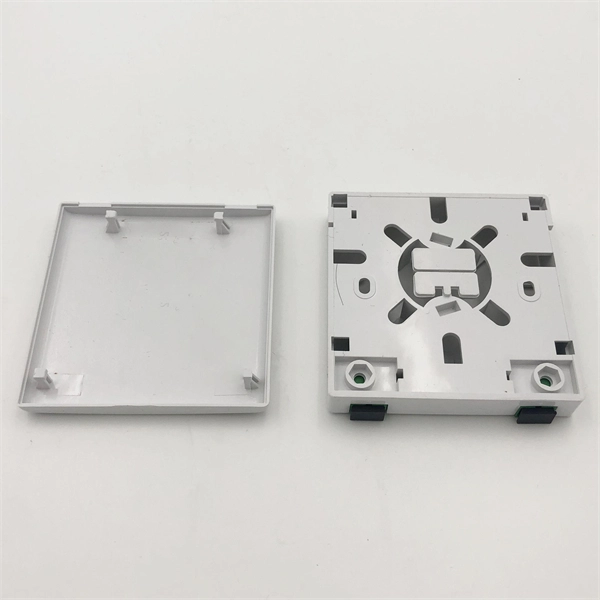
The terminal box provides: Strain relief: Cable clamps and grommets transfer tensile loads from fiber to chassis, preventing microbends and fiber breakage. Bend-radius control: Internal routing with ≥30 mm radius (typical for G. A2/B3 bend-insensitive fibers) minimizes induced attenuation. Slack. A Fiber Access Terminal (FAT), also known as a Fiber Access Terminal Box (ATB) or Fiber Distribution Terminal (FDT), is a key component found in optimized fiber optic access networks for FTTH implementations. It is a small enclosure that can house and protect the fiber optic cables, splices, and connectors. The fiber termination box. GAO Tek's fiber terminal boxes are devices used in fiber optic networks to terminate and manage fiber optic cables. Our boxes serve as a connection point for incoming and outgoing cables, providing cable termination, organization, and protection. GAO's box includes features such as cable. Fiber optic terminal box is a product use for different scenarios in FTTH construction, such as primary or secondary splitting. People usually use it to connect patch cables from the splitter to the indoor cables, meeting the demands for high-speed bandwidth services. It is widely used in optical fiber communication systems, such as Fiber to the Home (FTTH), Local.
[PDF]
CMP CXT type brass indoor and outdoor cable gland for use with all types of screened flexible wire braid (e. CY/SY), or wire braid armour cable. The cable gland provides an environmental seal on the cable outer sheath. Want to discuss this product with one of the CMP Technical Team? Call one of our team now on +44 191 265 7411 We have some exciting things in the pipeline - if you'd like to be the first to know please enter your email address below. Note: Supplied with Locknut & Washer. In summary, CXT is an abbreviation that can stand for various terms depending on the context, and its interpretation can vary across different fields such as technology, business, education, geography, government, law and other specialized areas. Features: Kit Contents: Additional Accessories available (upon request): The information in this datasheet is for. Operating Temp. Entry thread protection rating:. CMP CX Single seal brass cable gland suitable for braided, pliable wire and steel tape armoured cables. Our state-of-the-art cable testing facility ensures that every cable meets the highest standards of quality and compliance through continuous, rigorous testing. Where applicable, cables are.
[PDF]