
What is the main cause of attenuation in fiber? Attenuation in fiber mostly happens from absorption and scattering. The fiber material takes in some light as it moves. Both of these things make the signal weaker as it goes through the. Optical Signal Attenuation is the single greatest factor limiting the distance and performance of your network. Understanding it is crucial for anyone involved in data centers, telecommunications, or enterprise networking. This guide will demystify signal loss, explore its causes, and show you how. Optical fibers are a key component in modern communication systems, carrying signals over long distances. However, even the most advanced optical fiber suffers from attenuation, which is the loss of signal power as it travels along the fiber. Understanding the causes of signal loss and implementing mitigation strategies is essential for maintaining network efficiency. From infrastructure planners to telecom engineers. Optical fiber technology enables rapid data transmission over vast distances by guiding light signals through thin strands of glass. Losses can be introduced by various means such as intrinsic material absorption, scattering, bending, connector loss and more.
[PDF]

Even when a network is designed correctly, real-world conditions—fiber handling, connector cleanliness, splices, environmental stress, and aging—can gradually increase attenuation or introduce reflections and interference. Fiber optic patch cords are often treated as low-risk consumables, yet a large percentage of optical link failures originate at the patch cord level. Unlike backbone cables, patch cords are frequently connected, disconnected, bent, and handled by technicians, making them the most vulnerable. Optical attenuation is the gradual loss of flux (light intensity) as an optical signal travels through a fiber. Measured in decibels (dB), it's the logarithmic ratio of the output power to the input power. Every network has a "loss budget". Field guide for diagnosing high fiber optic attenuation. Learn to use the OTDR to identify contamination, micro-bends, and poor splices, ensuring your 400G network links remain within budget. This article explains practical, engineering-focused ways to mitigate signal. This measurement helps determine the efficiency of a fiber optic system. Several factors contribute to signal attenuation. These include absorption, scattering, and bending losses. Each factor plays a significant role in the overall performance of a network. Whether you're a network engineer, IT manager, or service provider, understanding these challenges and how to address them is critical for maintaining high-performance, reliable.
[PDF]
Connectorized attenuators often have a quite compact housing, essentially looking like a fiber-optic adapter. Some of these devices provide a fixed level of attenuation, quantified as the insertion loss in decibels. An optical attenuator, or fiber optic attenuator, is a device used to reduce the power level of an optical signal, either in free space or in an optical fiber. The basic types of optical attenuators are fixed, step-wise variable, and continuously variable. Optical attenuators are commonly used in. Fiber-optic attenuators are a specific type of optical attenuators which are used in fiber optics, e. for achieving a suitable signal level for a data receiver in a telecom system. It primarily ensures the power or amplitude of a signal is lowered without significantly distorting its waveform. The attenuator circuit will allow a known source of power to be reduced by a predetermined factor, which is usually expressed as decibels.
[PDF]
6Wresearch actively monitors the Palau Fiber Optics Cable Market and publishes its comprehensive annual report, highlighting emerging trends, growth drivers, revenue analysis, and forecast outlook. Our insights help. Est. Freight Cost? date (-30 days from arrival). Click here to find out more. Buyers typically pay for fiber optic cable by length, fiber type, and installation complexity. Main cost drivers include cable grade (indoor vs outdoor, armoured), distance, and labor for trenching, splicing, and termination. This guide presents ranges in USD and practical price estimates to help. CRU provides comprehensive, accurate and up-to-date price assessments and research reports for bare optical fibre across various key regional markets, combined with insights into the factors and events affecting markets. How does 6W market outlook report help businesses in making decisions? 6W monitors the market across 60+ countries Globally, publishing an annual market outlook report that analyses trends, key drivers, Size, Volume, Revenue, opportunities, and market segments.
[PDF]

Our list for Fiber optic products suppliers in Ecuador is one of the most comprehensive in the industry. As of May, 2026, we have compiled data on 23 verified listings. **** ZC Mayoristas Matriz. ****. As per the Volza's Ecuador Optical Fibers Exporters & Suppliers directory, there are 13 active Optical Fibers Exporters in Ecuador exporting to 37 Buyers. These facts are updated till 04-Jul-2025, and are based on Volza's Ecuador Exporters & Suppliers directory of Optical Fibers, sourced from 90+. We have local factory, delivery in any time and any place you want The most advanced technology and globle R&D team support A full set of test equipment that meets international standards Different cable design according to customer's needs LatamFiberHome was established in 2013. It's the first. Fabricante Cables Telecomunicaciones Opticable S. is an enterprise based in Ecuador. It operates in the Fiber Optic Cable Manufacturing industry. It was established on August 23, 2014. It currently has a total number of 1 (2024) employees. Contact Details: Purchase. Teldor is a well-established manufacturing company supplying cables to various industries around the world. As an industry-leading manufacturer of specialist cables, Teldor is a frontrunner in technical innovation. We provide an extensive range of cables designed to serve critical sectors such as.
[PDF]
Underground fiber optic cable carries the vast majority of the world's internet traffic, phone calls, and digital data. These cables are buried beneath streets, sidewalks, and rural land to connect homes, businesses, data centers, military installations, and city infrastructure. While the glass. Underground fiber optic cable is designed for direct burial or conduit installation and is widely used in FTTH networks, backbone infrastructure, and industrial communication systems. This guide explains underground fiber optic cable types, installation methods, burial depth, and practical. One of the key components driving this connectivity is underground fiber optic cable. It has been increasingly used in telecommunications networks around the world. Introduction of The Buried Fiber Optic Cable Fiber optic cables have revolutionized the way we transmit data, offering unparalleled speeds and reliability.
[PDF]

Since the earliest days of fiber optics, multimode cables have typically been color‑coded orange, black, or gray, while single‑mode cables are marked in yellow. For example, cable jacket color typically defines the fiber type, and can differ based on mode and performance level. These colors are typically chosen by industry standards bodies. However, there are some non-standardized colors and inconsistencies that you should be aware of. However, with the introduction of metallic connectors like FC and ST—whose bodies are difficult to color‑code—colored strain relief boots. Multimode fiber (MMF) is a kind of optical fiber mostly used in communication over short distances, for example, inside a building or for the campus. Multimode fiber optic cable has a larger core, typically 50 or 62. 5 microns that enables multiple light modes to be propagated. Because of this, more. Originally developed by the Electronic Industries Alliance (EIA) and the Telecommunications Industry Association (TIA), the TIA-598-D standard (formerly EIA/TIA-598) remains the most recognized color-coding system for optical fibers worldwide. On the right, the yellow patchcord indicates singlemode fiber and the blue connector means it is a regular PC polished connector, If it were an APC connector, it would be green. Perhaps nothing is.
[PDF]

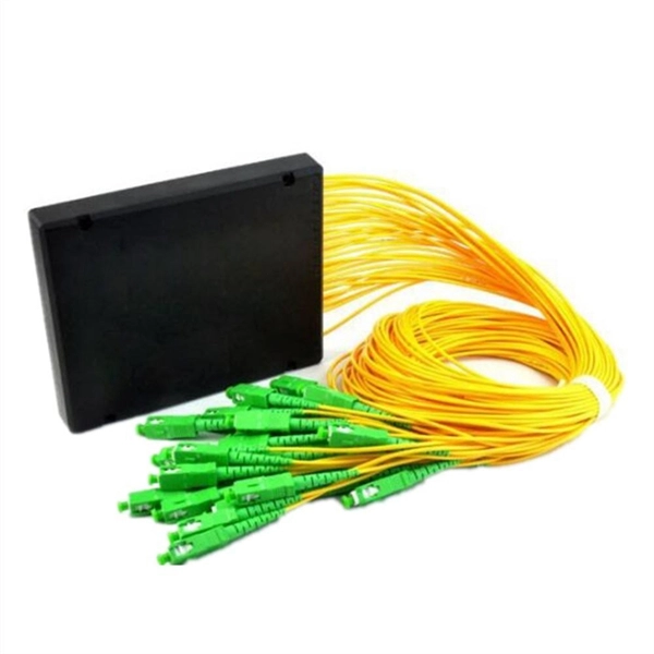
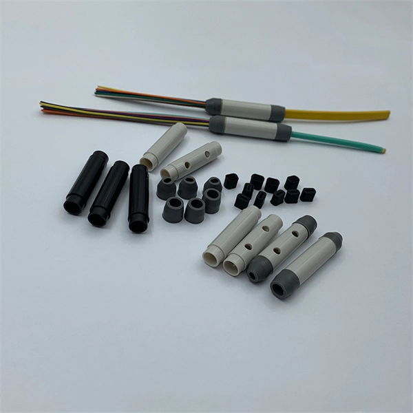
The main components of a splice box are the splice cassette that picks up the fibers and their reserves, and the front panel which contains different connectors for transmitting signals via copper or fiber optic cables. A splice box (also known as splice distributor) is a housing in which fiber optic cables begin or end. Fiber optics are fanned out in splice boxes that are situated at the end of fiber optic transmission paths. It typically consists of two parts: an outer housing and an internal structure. In this response, we will focus on the. The FSB series of indoor wall mount enclosures are designed for centralized splice-only applications. These boxes are well suited as optical cable splice collection points for DAS (Distributed Antenna Systems), MTU (Multi-Tenant Unit) commercial business applications, and MDU (Multi-Dwelling Unit). Fiber optic splice closures permanently connect two fiber optic cables together and have a splice that protects the components. The optical cable connection part, that is, the optical cable joint, is the part that protects the connection between two or more optical cables by the optical cable. Splicing refers to the permanent connection of two optical fibers to form a continuous optical connection.
[PDF]

Multimode Fiber Optic Receivers are devices designed to interpret information contained in optical signals transmitted through multimode fibers. These receivers convert the optical signals into electrical signals, allowing the data to be processed and utilized by electronic systems. Multimode Fiber. They convert electrical signals into optical signals for transmission over fiber-optic cables and reverse the process at the receiving end. Now, the term 'multimode' stems from the fact that these transceivers use multimode fiber (MMF) cables, which can carry multiple beams of light — or 'modes' —. Multi-mode optical fiber is a type of optical fiber mostly used for communication over short distances, such as within a building or on a campus. Multi-mode links can be used for data rates up to 800 Gbit/s. Most systems operate by transmitting in one direction on one fiber and in the reverse direction on another fiber for full duplex operation. For applications where long-haul transmission is unnecessary, multimode SFP modules offer a practical. They have a wider core (around 50 to 62. 5 micrometers), which enables multiple modes or light paths to coexist within the fiber, thus resulting in modal dispersion at shorter distances but reducing its efficacy over longer stretches. The choice between Single-Mode Fiber (SMF) and Multimode Fiber.
[PDF]

The terminal box provides: Strain relief: Cable clamps and grommets transfer tensile loads from fiber to chassis, preventing microbends and fiber breakage. Bend-radius control: Internal routing with ≥30 mm radius (typical for G. A2/B3 bend-insensitive fibers) minimizes induced attenuation. Slack. A Fiber Access Terminal (FAT), also known as a Fiber Access Terminal Box (ATB) or Fiber Distribution Terminal (FDT), is a key component found in optimized fiber optic access networks for FTTH implementations. It is a small enclosure that can house and protect the fiber optic cables, splices, and connectors. The fiber termination box. GAO Tek's fiber terminal boxes are devices used in fiber optic networks to terminate and manage fiber optic cables. Our boxes serve as a connection point for incoming and outgoing cables, providing cable termination, organization, and protection. GAO's box includes features such as cable. Fiber optic terminal box is a product use for different scenarios in FTTH construction, such as primary or secondary splitting. People usually use it to connect patch cables from the splitter to the indoor cables, meeting the demands for high-speed bandwidth services. It is widely used in optical fiber communication systems, such as Fiber to the Home (FTTH), Local.
[PDF]

Too many connections can cause too much signal loss. Clean your connections. As we discussed above, remove dirt, dust and oil from fingerprints with pen-style cleaners or alcohol wipes. Identify cable damage using a VFL tester. If identified, re-splice the cable. When issues like signal loss, slow speeds, or intermittent connectivity arise, systematic troubleshooting is key. This guide will walk you through diagnosing and resolving common fiber network issues efficiently. Why Do Fiber Networks Fail? Despite their robustness, fiber networks can fail due to:. Problems with fiber optic internet can range from signal attenuation to optic signal loss to equipment malfunctions. By shedding light on these common fiber internet problems and offering insights into preventative measures and advanced troubleshooting steps, we aim to empower network. Fiber optic troubleshooting is an essential skill for network administrators, technicians, and engineers responsible for maintaining and repairing fiber optic systems. These high-speed, high-capacity communication networks are increasingly replacing copper cables, offering superior performance and. Clean Fiber Optic connectors often to stop dirt and dust. Finding problems early saves money. It also stops long network downtime. Use the right tools to test for weak spots. These networks are the backbone of modern data transmission, offering incredible speeds and bandwidth.
[PDF]
You might have bad connections or lose signal if you bend them too much. Rough handling can also cause problems. Clean them often and manage them with care to stop these issues. If you act early, you will have less downtime. Your network will work better and stay smooth. Proper installation and regular maintenance of fiber optic patch cords play a crucial role in achieving optimized network performance, preventing signal errors, and extending service life. This guide addresses expert-certified best practices applied by professionals in the telecommunications, data. Patching operations must follow principles of neatness, aesthetic cabling, ease of operation, and minimal space usage within ODF frames, optical cross-connects, and integrated boxes. Patch cable lengths should be controlled with a surplus of no more than 500mm. Never use patch cables that are too. Effective fibre optic cable management is crucial for ensuring network reliability, performance, and long-term efficiency. Poorly routed cables, inadequate strain relief, and excessive bending can result in signal loss, increased maintenance, and costly downtime. Incorrect cable lengths can lead to signal attenuation, which refers to the loss of signal strength as it travels through the cable. Plan your fiber patch cord.
[PDF]

A fiber patch panel is a mounted enclosure—either rack-mounted or wall-mounted—used to terminate, manage, and interconnect multiple fiber optic cables. It acts as a hub for organizing splices and patch cords, streamlining fiber management and preserving signal integrity. Cable Organization:. Structured cabling is a standardized system to help you organize and install the cables and hardware that connect your different devices to your network (including computers, servers, cameras, or any other smart gadgets). Structured cabling uses consistent components, such as patch panels, jacks. A fiber distribution panel is also called a fiber patch panel. It helps you keep fiber optic cables neat in your network. You use this device to connect and separate fiber cables. It does not need power to work. Serving as the network's centralized junction, it provides secure ports for both incoming and outgoing. Fiber optical patch panels can help data center management cables. Do you know which types are available? What are their functions? This article will show you. With the development of data centers, the cabling infrastructure is getting larger and larger, the patch panel gives the data center a. A patch panel, including fiber patch panels and Ethernet patch panels, is a passive network device that centralizes, terminates, and organizes multiple copper or fiber cables.
[PDF]
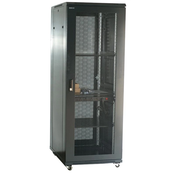
An Optical Distribution Frame (ODF) is a dedicated unit designed to organize, terminate, and interconnect fiber optic cables. It brings together fiber splicing, patching, and cable routing in a single structure, while shielding sensitive connectors and splices from mechanical. In the complex architecture of fiber optic networks, the Optical Distribution Frame (ODF) serves as the linchpin for organizing, protecting, and distributing optical signals. Whether in data centers, telecom central offices, or enterprise network rooms, ODFs enable efficient fiber management. Among the many solutions available, the Optical Distribution Frame (ODF) plays a central role in organizing, protecting, and simplifying fiber management in telecom rooms, central offices, and data centers. As data centers, enterprises, telecom operators, and smart-building infrastructures deploy increasingly dense fiber links, ODFs provide the structured. Optical Distribution Frames (ODF) are indispensable components in optical communications networks. They provide efficient fiber optic management, connectivity, and protection. Whether you are building a data center, deploying FTTx networks, or managing the telecom systems, the selection of suitable ODF is very important since the fiber connections are optimized.
[PDF]

It can be seen from the above that the aggregation switch has functions such as source address, destination address filtering, real-time policy, security, network isolation, and segmentation. Compared with access switches, aggregation switches have better performance and higher. What is an Aggregation Switch and How Does it Work? An aggregation switch consolidates data traffic from multiple network access switches into a single high-bandwidth link directed toward a core network or data center. The primary function of an aggregation switch is to aggregate and forward data. A fiber optic aggregation switch is a high-capacity network device designed to integrate and manage multiple fiber optic connections from access layer switches into fewer and faster uplink connections to the core network. It is essential for larger networks requiring efficient data flow. You may also. All-optical Ethernet switches are a type of switch that provides optical uplink and downlink ports, making them an ideal choice for building an all-optical campus network. They can function as core, aggregation, and access devices on campus networks and connect to upstream and downstream devices. As the physical entity of the aggregation layer, the aggregation switch's primary function is to aggregate the data of the access layer switch and forward it to the core switch to reduce the burden on the core layer. Cisco's aggregation switch What is the Role of the Aggregation Switch in the.
[PDF]

