Connectorized attenuators often have a quite compact housing, essentially looking like a fiber-optic adapter. Some of these devices provide a fixed level of attenuation, quantified as the insertion loss in decibels. An optical attenuator, or fiber optic attenuator, is a device used to reduce the power level of an optical signal, either in free space or in an optical fiber. The basic types of optical attenuators are fixed, step-wise variable, and continuously variable. Optical attenuators are commonly used in. Fiber-optic attenuators are a specific type of optical attenuators which are used in fiber optics, e. for achieving a suitable signal level for a data receiver in a telecom system. It primarily ensures the power or amplitude of a signal is lowered without significantly distorting its waveform. The attenuator circuit will allow a known source of power to be reduced by a predetermined factor, which is usually expressed as decibels.
[PDF]

The V-groove substrate is the heart of the Fiber Array, providing precise alignment for the optical fibers. This substrate, typically made from silicon, glass, or ceramic, features a series of V-shaped grooves etched with sub-micron accuracy. A fibre array is an array formed by mounting a bundle of fibres or a strip of fibres on a substrate at specified intervals using a V-groove substrate. Typically, such an array is formed only for the very end of the fibre bundle, rather than over the entire length of the fibre. The purpose of the. What is a Fiber Array? Fiber arrays (or fiber-optic arrays or fiber array units) are one- or two-dimensional arrays of optical fibers. As for these V-groove optical fiber arrays, or the so-called optical V groove array, they are normally fixed into the grooves with epoxy and pressed by a glass cover. Fiber optic arrays in optical communications mainly include a substrate, a platen, and an optical fiber. Usually, multiple. Fiber Arrays (FAs), as high-precision, high-performance optical components, have become indispensable core elements in fields such as optical communications, photonic integration, and laser processing.
[PDF]

A cable ladder tray system is characterized by its two longitudinal side rails connected by individual rungs, resembling a ladder. This design provides exceptional strength and ventilation, making it ideal for supporting heavy power cables and a large volume of wiring. Explore our full collection of Metallic Ladder 3D Drawings, including horizontal fittings, vertical fittings and metallic tray. Filter Results Results refresh instantly as you filter. Used to identify and differentiate offerings within a particular product line. Ladder tray is the most common and the most economical type of tray, also providing maximum ventilation for cabling. Rungs are fastened to the side. Our cable tray design considerations guide details key factors to consider when designing cable tray systems for industrial and commercial applications. Designed to provide maximum ventilation and ease of cable management, cable ladder trays are ideal for heavy-duty applications where multiple cables need to be organized and. Hubbell's NEXTFRAME® Ladder Tray is the effective and widely used cable runway that supports and delivers bundles of cable between cabinets, racks, and closets, along walls, and suspended from ceilings. The Ladder Tray features light, rugged, tubular steel construction. Think of it as a sophisticated “highway” for cables, keeping them organized, protected, and easily accessible. A complete system is made up of.
[PDF]
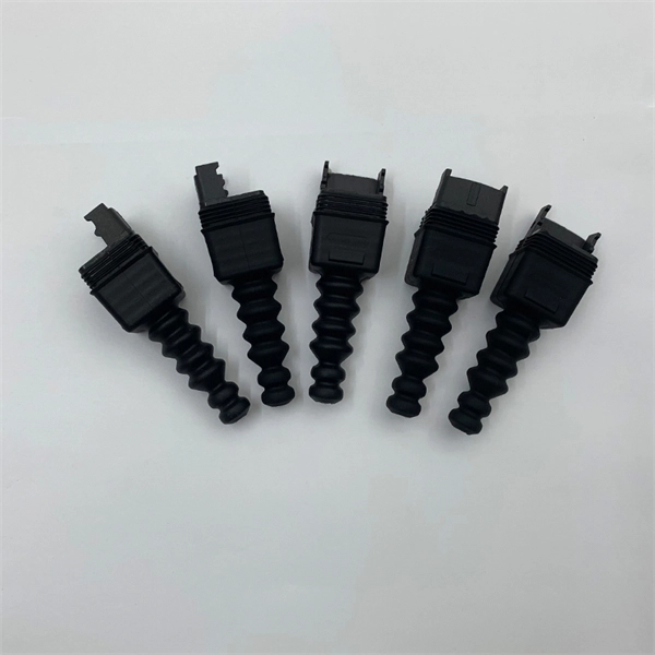
Pigtail, also known as pigtail, has only one end with a connector, and the other end is a broken end of a fiber optic cable core. It often appears in fiber optic terminal boxes. (couplers, jumpers, etc. are also used between. Long tail fibers consist of a phage-proximal and a phage-distal rod, each around 80 nm long and attached to each other at a slight angle. The phage-proximal rod is formed by a homo-trimer of gene product 34 (gp34) and is attached to the phage-distal rod by a monomer of gp35. are also used between them). One. The tailed phage T4 encodes a specialized device for this purpose, the long tail fiber (LTF), which allows the virus to move on the bacterial surface and find a suitable site for infection. Consequently, the infection efficiency of phage T4 is one of the highest, reaching the theoretical value of. Bacteriophages, often called phages, are viruses that infect and replicate within bacteria. These tiny biological entities play a significant role in microbial ecosystems. Tail fibers are structures on the phage that mediate their initial interaction with bacterial hosts, allowing them to recognize. The tail (Fig. Infection is initiated with the reversible attachment of six long tail fibers (LTFs) to the cell's outer layer of lipopolysaccharides, followed by transformation of the.
[PDF]
Shop for Suction Cup Containers at Walmart. Live better. Check each product page for other buying options. Price and other details may vary based on product size and color. Need help?. Uses item details. Price when purchased online. Includes import fees. Estimated delivery dates - opens in a new window or tab include seller's handling time, origin ZIP Code, destination ZIP Code and time of acceptance and will depend on shipping service. Polycarbonate suction cup displays used across the world to showcase YOUR product and capture sales. The Best Tool To Gain Sales Through Cross Merchandising. Versatile racks that work with just about any product that you need it for. Get your merchandise in line of sight! Showcase your best seller. This functional shower and tub organizer provides storage space for a variety of bathroom necessities such as shampoo and conditioner bottles, body wash, soap, shaving cream, and more while the transparent plastic sides and open top provide visibility and easy access. Featuring Power Lock suction. The Acrylic Box with Suction Cups is a clear acrylic display box that can be secured to countertops with the suction cups at each corner. It is a great way to display cosmetics, samples, giveaways, candy, merchandise and more on the store counter or front desks. The acrylic clear box display case.
[PDF]

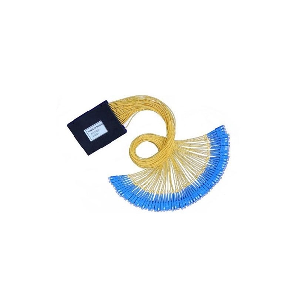
Fiber splitters serve as essential components in optical networks. These devices divide an optical signal from a single input into multiple outputs. This process enables efficient signal distribution across various network points. Fiber splitters function without the need for external. In the intricate web of modern fiber optic networks, where data travels at the speed of light across continents, fiber optic splitters play a silent yet pivotal role. These unassuming devices enable a single optical signal to be divided into multiple paths, making them indispensable for sharing. A fiber splitter, also known as a beam splitter, is a passive optical device that splits an optical signal into multiple signals. By dividing a single optical signal into multiple signals, fiber. Fiber optic splitters are vital in modern communication networks. Fiber optic splitters, such as plcsplitter and fbt splitters, are crucial in maintaining signal integrity, with considerations for IL (Insertion Loss) and RL (Return Loss). They are integral components in the world of telecommunication and data networking, crucial to maintaining reliable and efficient communication infrastructures. There are two primary.
[PDF]

Fusion splicing is the most widely used method of splicing as it provides for the lowest loss and least reflectance, as well as providing the strongest and most reliable joint between two fibers. Virtually all singlemode splices are fusion. There are two main methods of splicing: mechanical splicing and fusion splicing. This blog will delve into the nuances of each method, comparing their costs, labor efficiency, network performance, and more, to help you decide which splicing technique is best suited for your needs. Why splice? Fiber. Fusion splicing is the process of fusing or welding two fibers together usually by an electric arc. Fiber splicing means joining two optical fibers (permanently or temporarily) such that light guided in one fiber and reaching the joint (splice) can be transferred into the second fiber with low insertion loss. Another method of connecting optical fibers is termination or connectorization, which consists of processing the end of a fiber optic bundle so that it can be connected to other fibers or devices through fiber optic. Fiber Optic Cable is a form of modern network cable that has a far greater capacity than electrical communication connections. Splicing is typically required during cable installation, maintenance, or network expansion. The goal is to achieve the lowest possible optical loss (signal.
[PDF]
Networking cabinets are not automatically fire proof. A standard network cabinet is mainly designed for equipment installation, cable organization, ventilation, and routine physical protection, while a fire-resistant solution is built and tested for defined fire performance. Real fire protection. This IT server cabinet fireproof is the solution for highest fire and IT security requirements. As a complete, compact data center with all infrastructures such as air conditioning, UPS, monitoring, etc. Advantages: Nothing happens to your most. Fireproof server cabinets and other technologies like them are the new standard, and businesses are retrofitting existing configurations with newer server room fire suppression systems to minimize risk. Prevention these days saves a small fortune in the long term. This is one of the only ways a smoldering fire or. Rack mount fire protection solutions are designed for installation into server racks and server cabinets to provide fast and effective fire detection and suppression and reduce the threat of fire to business continuity. When sizing a rack mounted fire suppression unit it is important to measure the. The modular Smart Cage Room system allows the server room to be fully utilised in its available height. Accessories, UPS, air conditioning and cabling can be placed where they perform their function best. The use of space is therefore flexible. The open-ended height and free scalability support the.
[PDF]
The bare fiber end is designed to be fusion spliced or mechanically spliced to the fiber optic cable in the field. This design makes pigtails the ideal choice for applications where fibers from a large cable must be terminated at an ODF (Optical Distribution Frame), terminal box, or. By combining factory-installed connectors with spliced bare fiber, pigtails ensure that network installers can create fast, reliable, and cost-effective terminations. Without pigtails, every termination in an ODF, terminal box, or splice closure would require field-installed connectors—an approach. ■ What is a fiber optic pigtail cable? A pigtail fiber indicates a short length of optical fiber cable that has a pigtail connector (for example, SC, FC, ST, LC, etc. This. A fiber pigtail is typically a fiber optic cable with one end factory pre-terminated fiber connector and the other exposed fiber. It is usually suitable for field termination using a mechanical or fusion splicer. Its primary function is to connect active network devices (e., switches, routers, transceivers) to passive components (e., patch panels, ODFs) or other devices. Think of it as a.
[PDF]

Cable laying services install fiber optic cable or copper cable in buildings and office complexes, or over large distances. They are staffed by cable technicians who perform cable preparation, jointing, termination, testing, commissioning, maintenance, and troubleshooting tasks. Installing fiber optic cables underground involves far more than digging trenches and placing cables. It forms a critical backbone for modern communication networks across both urban and rural environments. Project success depends on careful planning, precise installation practices, and proper. Installing underground fiber optic cables is critical to establishing high speed internet infrastructure that delivers reliable connectivity for businesses nationwide. Unlike traditional copper systems, fiber optic cables require specialized handling techniques and precise installation methods to. These skilled professionals ensure that your home or business is equipped with the latest fiber optic technology, providing blazing-fast Internet speeds and robust connections. This guide walks you through the entire process of fiber cable installation, from the initial assessment to the final. This involves burying or installing fiber-optic cables along predetermined routes. During this phase, locators identify existing utilities to prevent damage.
[PDF]

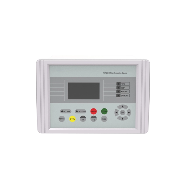
It can be seen from the above that the aggregation switch has functions such as source address, destination address filtering, real-time policy, security, network isolation, and segmentation. Compared with access switches, aggregation switches have better performance and higher. What is an Aggregation Switch and How Does it Work? An aggregation switch consolidates data traffic from multiple network access switches into a single high-bandwidth link directed toward a core network or data center. The primary function of an aggregation switch is to aggregate and forward data. A fiber optic aggregation switch is a high-capacity network device designed to integrate and manage multiple fiber optic connections from access layer switches into fewer and faster uplink connections to the core network. It is essential for larger networks requiring efficient data flow. You may also. All-optical Ethernet switches are a type of switch that provides optical uplink and downlink ports, making them an ideal choice for building an all-optical campus network. They can function as core, aggregation, and access devices on campus networks and connect to upstream and downstream devices. As the physical entity of the aggregation layer, the aggregation switch's primary function is to aggregate the data of the access layer switch and forward it to the core switch to reduce the burden on the core layer. Cisco's aggregation switch What is the Role of the Aggregation Switch in the.
[PDF]

The network cabinet provides space for integrated cabling and the cable management interface for the smart module. Diverse monitoring devices are available. Determine the installation plan based on the configurations. Figure 14-1 shows the installation positions for certain monitoring devices for your reference. Use an. Huawei Methods-M series of cabinets offer data centers with fundamental physical support to house relevant devices. These cabinets feature high reliability, safety, compatibility and availability. They have been widely applied in various data centers. The depth stride of the mounting bars is 25 mm. High quality cold rolled steel sheet and anti-corrosion, no rust. Email: Vivian@E-Flourish. Com / Room A801, Huayi Building, Wuhe Road, Bantian, Longgang District, Shenzhen, Guangdong, China We supply UPS power supplier and batteries of APC, Emerson, Santak, Panosonic, CSB, YUASA, LEOCH and etc. MTS9300A indoor Integrated Intelligent Site for 5G network MTS9304A-HD16A1 MTS9304A-HA16A1 MTS9304A-HA2001 Product Description Huawei MTS9000 and MTS9300A provide power in outdoor environments for network transmission sites, fixed access sites, and wireless Base Transceiver Station (BTS) sites. The distance between the front and rear mounting bars can be adjusted by a. Once receive your question, the supplier will answer you as soon as possible. Enter between 20 to 4,000 characters. Click here to contact the supplier through an inquiry.
[PDF]

Even when a network is designed correctly, real-world conditions—fiber handling, connector cleanliness, splices, environmental stress, and aging—can gradually increase attenuation or introduce reflections and interference. Fiber optic patch cords are often treated as low-risk consumables, yet a large percentage of optical link failures originate at the patch cord level. Unlike backbone cables, patch cords are frequently connected, disconnected, bent, and handled by technicians, making them the most vulnerable. Optical attenuation is the gradual loss of flux (light intensity) as an optical signal travels through a fiber. Measured in decibels (dB), it's the logarithmic ratio of the output power to the input power. Every network has a "loss budget". Field guide for diagnosing high fiber optic attenuation. Learn to use the OTDR to identify contamination, micro-bends, and poor splices, ensuring your 400G network links remain within budget. This article explains practical, engineering-focused ways to mitigate signal. This measurement helps determine the efficiency of a fiber optic system. Several factors contribute to signal attenuation. These include absorption, scattering, and bending losses. Each factor plays a significant role in the overall performance of a network. Whether you're a network engineer, IT manager, or service provider, understanding these challenges and how to address them is critical for maintaining high-performance, reliable.
[PDF]
Optical cable tray is a system designed to protect and route fiber optic patch cords, cable assemblies to and from network cabinets, ODF and other terminal devices. Ducting offers ideal solutions for optical raceway requirements and application with pleasing appearance and easy. Our Fiber Cable Tray System is a comprehensive raceway solution for data center, enterprise, central office, and mobile switching center applications. Designed to route and protect fiber optic and high-performance copper cabling to and from network cabinets, distribution frames, and other terminal. Cable trays are a foundational part of this infrastructure, offering a secure, scalable, and organized method of managing fiber routing across diverse environments.
[PDF]

The typical specification range of return loss of a fiber connector is -15 dB to -60 dB. Return loss is also known as reflection loss. It indicates the amount of signal reflected back to the transmitting end. Return loss refers to the power loss caused by the reflection of part of the signal back to the signal source during transmission due to the discontinuity of the transmission. Insertion loss, also known as attenuation, is the loss of optical power that occurs when light passes through a fiber optic connector. It is caused by factors such as misalignment, air gaps, and imperfections in the connector components. The lower the insertion loss, the better the performance of. Reflectance (which has also been called "back reflection" or optical return loss) of a connection is the amount of light that is reflected back up the fiber toward the source by light reflections off the interface of the polished end surface of the mated connectors and air. It is also called. Insertion Loss (IL) is the amount of optical power lost as the signal travels from one point to another in a fiber optic link, usually across connectors or splices. Formula for. In optical fiber communication, insertion loss and return loss are two important parameters to evaluate the quality of interfaces between some optical fiber components, such as optical fiber connector, fiber patch cable, pigtail fiber, etc. While it's natural to have.
[PDF]