A protective relay is an intelligent electrical device designed to detect faults in power systems and initiate corrective actions such as tripping a circuit breaker. · Detection of the presence of a fault. · To close the trip circuit and operate the circuit breaker to isolate the faulty system from the healthier one. What is a protection relay? What is the purpose of protection. An electrically operated switch like a relay plays a key role in controlling an electrical circuit through an independent low-power signal, otherwise used where a number of circuits should be controlled through the single signal. Its main purpose is to safeguard electrical equipment like transformers, generators, and transmission lines from damage due to. A protection relay is a crucial component of electrical systems that safeguard infrastructure, employees, and equipment from electric problems and malfunctions. It functions as a watchdog by constantly surveying multiple system components including voltage, current, frequency, and phase angle. In other words, the prime function of protective relays is the timely and.
[PDF]

Setting up a fiber optic network requires specific equipment to ensure optimal performance. Key components include fiber optic cables, ONT, OLT, routers, Ethernet cables, NICs, Optical Power Meters, and Fiber Optic Splicers. In this article, we explore ten critical fiber optic components—from fiber optic cables to drop wire clamps—and their indispensable roles in building robust, future-ready networks. Fiber Optic Cable: The Lifeline of Data Transmission Fiber Optic cables are the highways of fiber optic networks. Let's break down the essential fiber optic components that make your high-speed connection possible. Inside these cables are incredibly thin strands of glass that transmit your data as pulses of light. Whether for residential or commercial use, investing in the right. Before diving into the tools used for installation and maintenance, it's vital to understand the core components that constitute a fiber optic network. These are the physical elements that carry the light signals, enabling high-speed data transmission. Each component plays a critical role, and. At the heart of any fiber internet infrastructure are the fiber-optic cables themselves. Renowned for their efficiency in carrying data over long distances, fiber optic cables transmit that.
[PDF]

The main components of a splice box are the splice cassette that picks up the fibers and their reserves, and the front panel which contains different connectors for transmitting signals via copper or fiber optic cables. A splice box (also known as splice distributor) is a housing in which fiber optic cables begin or end. Fiber optics are fanned out in splice boxes that are situated at the end of fiber optic transmission paths. It typically consists of two parts: an outer housing and an internal structure. In this response, we will focus on the. The FSB series of indoor wall mount enclosures are designed for centralized splice-only applications. These boxes are well suited as optical cable splice collection points for DAS (Distributed Antenna Systems), MTU (Multi-Tenant Unit) commercial business applications, and MDU (Multi-Dwelling Unit). Fiber optic splice closures permanently connect two fiber optic cables together and have a splice that protects the components. The optical cable connection part, that is, the optical cable joint, is the part that protects the connection between two or more optical cables by the optical cable. Splicing refers to the permanent connection of two optical fibers to form a continuous optical connection.
[PDF]
A fiber array (FA) is an arrangement where a bundle of optical fibers or a fiber ribbon is mounted onto a substrate with predefined spacing, typically using a V-groove baseplate. In optical communications, a fiber array mainly consists of a baseplate, a pressure plate, and optical. Fiber Arrays (FAs) are foundational components that enable this alignment by organizing multiple optical fibers into a compact and highly accurate format. Whether integrated into planar lightwave circuits (PLCs), optical switches, or high-speed transceivers, FAs play a vital role in ensuring. What is a Fiber Array (FA)? A Fiber Array, commonly abbreviated as FA, is a critical interface component in Silicon Photonics (SiPh) packaging, Photonic Integrated Circuits (PIC), and Co-Packaged Optics (CPO) architectures. It is responsible for efficiently coupling "external optical fibers" with. Fiber arrays, also known as fiber-optic arrays or fiber array units, are crucial components in the field of photonics. These arrays can be one-dimensional or two-dimensional, consisting of optical fibers that are often arranged at the end of a fiber bundle. What is a Fiber Array? A fiber array is an optical device that aligns and secures a bundle of. and data center applications. Often, such an array is formed only for the very end of a bundle of fibers, rather than over the whole fiber length. The purpose of such an array is typically either coupling light from.
[PDF]

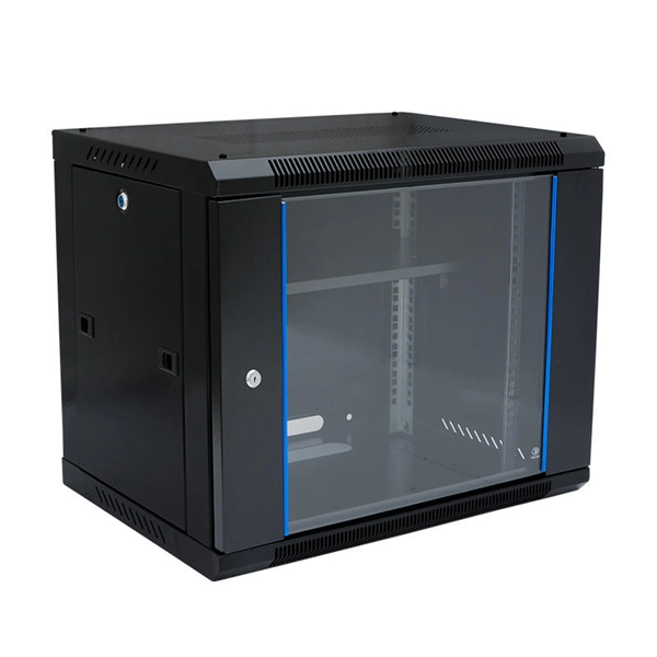
It can be seen from the above that the aggregation switch has functions such as source address, destination address filtering, real-time policy, security, network isolation, and segmentation. Compared with access switches, aggregation switches have better performance and higher. What is an Aggregation Switch and How Does it Work? An aggregation switch consolidates data traffic from multiple network access switches into a single high-bandwidth link directed toward a core network or data center. The primary function of an aggregation switch is to aggregate and forward data. A fiber optic aggregation switch is a high-capacity network device designed to integrate and manage multiple fiber optic connections from access layer switches into fewer and faster uplink connections to the core network. It is essential for larger networks requiring efficient data flow. You may also. All-optical Ethernet switches are a type of switch that provides optical uplink and downlink ports, making them an ideal choice for building an all-optical campus network. They can function as core, aggregation, and access devices on campus networks and connect to upstream and downstream devices. As the physical entity of the aggregation layer, the aggregation switch's primary function is to aggregate the data of the access layer switch and forward it to the core switch to reduce the burden on the core layer. Cisco's aggregation switch What is the Role of the Aggregation Switch in the.
[PDF]

Main Switch: This switch controls all electricity coming into the box. Busbar: A metal strip spreads power to each circuit. Send the details below and we will recommend a matched DB configuration and provide a quotation: Number of ways (circuits): 4 / 6 / 8 / 12 / 18 / 24. Voltage & phase: 230V 1P / 400V 3P. What Is a Distribution Box (DB / Distribution Board)? A distribution box (distribution board / DB box) receives. What is a Distribution Box? A distribution box, or DB box, is a circuit breaker enclosure. It is a vital part and central hub of any electrical system. The hub distributes electrical power from a single input source to various circuits throughout a building. Whether it's a home, office, or factory. Learn about the internal structure of a distribution box, its components, functions, and key types. Acting as a central hub, a distribution box receives electricity from the main power. The internal structure of the distribution box is designed to safely distribute power from the main power source to multiple branch circuits. It provides convenience for protection, control and maintenance. This article discusses the construction of the distribution box, its functional divisions. Distribution boxes come in several types, which can be grouped by installation method, material, and function. By Installation Position: Open Installation: These boxes are fixed on the surface of walls or panels. They are easy to access and maintain, but the wiring remains visible.
[PDF]

The connectors used in cold splicing typically consist of two parts: a ferrule and a body. The ferrule is a small, cylindrical piece that is designed to hold the fiber in place and maintain its alignment with the other fiber. Optical fiber cold splice technology is based on the use of mechanical connectors to join two fiber-optic cables. Get the wrong connector type, the wrong polish, or skip proper fusion splicing technique—and you're looking at elevated signal loss, increased back reflection, and a. Fiber optic joints or terminations are made two ways: 1) splices which create a permanent joint between the two fibers or 2) connectors that mate two fibers to create a temporary joint and/or connect the fiber to a piece of network gear. This is essential for extending network reach, repairing breaks, or connecting cables in data centers and telecom infrastructure. The goal is to align the microscopic glass cores (typically. In this guide, we cover the basics of fiber optic splicing, how to perform splicing using two different methods, and finally some best practices to perform good fiber splicing. What is Fiber Optic Splicing and Why is it Needed? – #1.
[PDF]
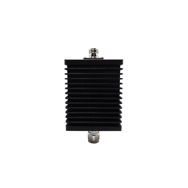
Optical fibers can be used as sensors to measure, , and other quantities by modifying a fiber so that the quantity to be measured modulates the,,, or transit time of light in the fiber. Sensors that vary the intensity of light are the simplest, since only a simple source and detector are required. A particularly useful feature of intrinsic fiber-optic sensors is that they can, if required, provide distributed sensing over very large distances.
[PDF]

Multimode Fiber Optic Receivers are devices designed to interpret information contained in optical signals transmitted through multimode fibers. These receivers convert the optical signals into electrical signals, allowing the data to be processed and utilized by electronic systems. Multimode Fiber. They convert electrical signals into optical signals for transmission over fiber-optic cables and reverse the process at the receiving end. Now, the term 'multimode' stems from the fact that these transceivers use multimode fiber (MMF) cables, which can carry multiple beams of light — or 'modes' —. Multi-mode optical fiber is a type of optical fiber mostly used for communication over short distances, such as within a building or on a campus. Multi-mode links can be used for data rates up to 800 Gbit/s. Most systems operate by transmitting in one direction on one fiber and in the reverse direction on another fiber for full duplex operation. For applications where long-haul transmission is unnecessary, multimode SFP modules offer a practical. They have a wider core (around 50 to 62. 5 micrometers), which enables multiple modes or light paths to coexist within the fiber, thus resulting in modal dispersion at shorter distances but reducing its efficacy over longer stretches. The choice between Single-Mode Fiber (SMF) and Multimode Fiber.
[PDF]
A junction box contains two trade size 3 raceways on the left side and one trade size 3 raceway on the right side. raceway on the right side, and one 3-in. raceways on. Pull boxes, junction boxes, and conduit bodies must be sized to allow conductors 4 AWG and larger to be installed without damage to the conductor insulation. The NEC provides sizing requirements in 314. Keep in mind these requirements address conductors used for general wiring, such as those. Article 370 covers the installation and use of all boxes (and conduit bodies) used as outlet, junction, or pull boxes, depending on their use. You're reading an older article from ELECTRICAL CONTRACTOR. Some content, such as code-related information, may be outdated. Visit our homepage to view the. When conductors enter an enclosure with a removable cover, such as a conduit body or wireway, the minimum distance from the raceway entry to the removable cover is the bending distance listed in Table 312. 6 (A) for one conductor per terminal [314. This approach helps in the safe organization of wires. To stop a fire from beginning or spreading, sparks are contained by fireproof connections and boxes. In this reading, we will delve into the definition of a. For example, a box is needed for eight 2-inch conduits. Each conduit will contain 2/0 conductors that will be spliced within the box. What is the minimum length required for the left/right (“X”) dimension? The minimum distance required because of the.
[PDF]

A typical fiber optic splice enclosure consists of several key components that work together to protect and organize the fiber splices. Standard enclosures contain: 1) Housing, 2) Cable fixation clamps, 3) Splice trays, 4) Sealing system. A splice box (also known as splice distributor) is a housing in which fiber optic cables begin or end. Fiber optics are fanned out in splice boxes that are situated at the end of fiber optic transmission paths. Optical cable joint box The optical cable joint box permanently connects two optical cables together and has a joint part for protecting components. The optical cable connection part, that is, the optical cable joint, is the part where the. An optical cable split fiber box, also known as a fiber distribution box or fiber optic splice closure, is a device used to terminate, splice, and distribute optical fibers. In this response, we will focus on the. This guide optimizes the original text by delving deeper into the three pillars of fiber network longevity: the impact of splicing technology, the strategic selection of splice boxes, and the essential maintenance protocols needed to ensure sustained, high-speed functionality. Fibre optic cables are manufactured in standardized lengths –.
[PDF]

It connects to two independent power sources, enabling automatic switching to a secondary source during primary source failures. This seamless transition prevents disruptions to connected devices and enhances operational reliability. A dual power switching box is precisely the kind of gadget that guarantees a constant flow of electricity as it enables the user to shift the operational state between two different energy supplies. It can be found in homes, workplaces, factories, and anywhere else where sudden cuts of energy can. The ATS Dual Power Distribution Box plays a pivotal role in providing efficient low-voltage power solutions, ensuring that power flows seamlessly, even in the event of an outage. This comprehensive guide offers insights into the mechanisms and benefits of the ATS Dual Power Distribution Box. Transfer switches and sub panel boxes are key components in dual power switching cabinets. Transfer switches automatically switch between power sources during outages, ensuring uninterrupted power and system reliability. This redundancy ensures that if one power source fails, the other can immediately take over, minimizing downtime and preventing. A dual power switch helps you manage two power sources for one system. You can use it to keep your equipment working if the main power stops. This device quickly changes from the main supply to a backup source. This seamless transition.
[PDF]

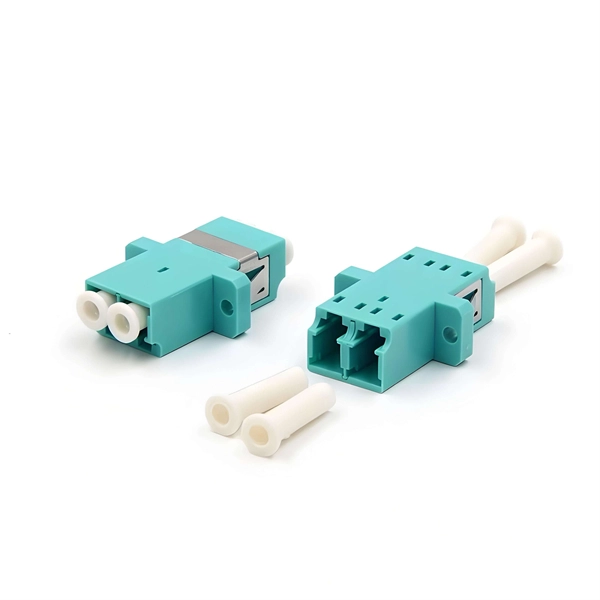
Multi-mode fiber optic patch cords utilize a larger core size, typically around 50-100 microns, allowing them to carry multiple modes of light. This design enables the transmission of data over relatively short distances with high bandwidth capabilities. A fiber-optic patch cord is a fiber-optic cable capped at each end with connectors that allow it to be rapidly and conveniently connected to telecommunication equipment. This is known as interconnect-style cabling. A fiber-optic patch cord is constructed from a core with a high refractive. These short fiber optic cords connect transceivers, switches, patch panels, and servers. Without them, even the best optical modules and switches cannot deliver performance. As data rates increase from 10G → 100G → 400G → 800G, patch cables must handle more bandwidth, more density, and stricter. Fiber optic patch cords, also known as fiber optic patch cables or fiber jumpers, are indispensable components in modern optical networks. They act as the critical link for interconnecting devices like optical switches, servers, and distribution frames. Understanding the various technical. Fiber patch cables, also called fiber-optic patch cords, are cables typically containing one or two optical fibers, which are equipped with standardized fiber connectors on both ends. The function of the fiber patch cord.
[PDF]

Usually, the 10G/25G grey light optical modules with a short transmission distance are applied for connecting AAU/DU with WDM/OTN/SPN. The connections between WDM/OTN/SPN network devices can be achieved by 10G/25G/50G/100G dual-fiber or single-fiber bidirectional. Compared with Draft A (2013-07-30), this issue includes the following new topic: 2. This section describes engineering specifications of an AAU, including input power and equipment specifications. 7. In 2/3/4G networks, 10Gbps optical modules are generally enough for CPRI interfaces. In 5G networks, CPRI is also upgraded to eCPRI. Currently, 5G of the bearer network mainly uses 25Gbps optical modules. Next, ETU-LINK will introduce the types of optical modules used by 10G SFP+ and 25G SFP28. What is the difference between the 5G bearer network and the traditional optical transmission network? The main difference is that 5G fronthaul needs to support CPRI/eCPRI protocol. Most of the AAU of 5G base stations are deployed outdoors. In order to resist harsh environments such as high. The optical modules used to connect BBU and RRU devices are optical modules and optical fibers. Product Versions The following table lists the product versions related to this document. 25G SFP optical module adopts the wavelength of 850nm, with an operating.
[PDF]
Picking up the best router for fiber internet isn't just about going to the market and choosing one of the best wireless routers. Instead, you need to carefully look at its specs, performance, and the type of securit.
[PDF]