Distance relays, also known as impedance relay, differ in principle from other forms of protection in that their performance is not governed by the magnitude of the current or voltage in the protected circuit but rather on the ratio of these two quantities.OverviewIn, a protective relay is a device designed to trip a when a is detected. The first protective relays were electromagnetic devices, relying on coils operating on moving par. Electromechanical protective relays operate by either, or. Unlike switching type electromechanical with fixed and usually ill-defined operating voltage thresholds. Electromechanical relays can be classified into several different types as follows: "Armature"-type relays have a pivoted lever supported on a hinge or knife-edge pivot, which carries a moving contact. These relays may.
[PDF]
The AC mains high and low voltage cut off circuit I have explained in this article is very easy to build and yet very reliable and accurate. The circuit utilizes a single IC LM 324for the necessary detection and instant.
[PDF]

Optical cable lines lightning protection and strong current protection are achieved by avoiding, guiding or discharging them underground to prevent lightning and strong current from causing damage to the optical cable lines themselves, communication equipment and personnel. Since the lightning. ntly, there are a limited number of industry documents that address the requirements for optical fiber cables near high voltage circuits. One standard that has been developed by the Institute of Electrical and Electronics Enginee s, Inc (IEEE) is 1222, “IEEE Standard for All-Dielectric. The Fiber Optic Association, Inc. (FOA) was founded in 1995 to help develop the workforce to build the fiber optic networks to support a rapid expansion in communications and the Internet. ” It defines the requirements for ADSS cables placed aerially in a high. This Recommendation provides a procedure to protect the telecommunication lines using fibre optics against direct lightning discharges to the line itself or to the structures that the line enters. The protection procedure is related to the exposure of the line to direct lightning discharges and. Armored Cable: For direct burial or areas prone to crushing, use armored fiber optic cables that have an additional layer of metallic or non-metallic protective sheathing. Cable Trays and Ladders: In data centers and industrial settings, use cable trays or ladders to support runs, keeping them off.
[PDF]

A protective relay is an intelligent electrical device designed to detect faults in power systems and initiate corrective actions such as tripping a circuit breaker. · Detection of the presence of a fault. · To close the trip circuit and operate the circuit breaker to isolate the faulty system from the healthier one. What is a protection relay? What is the purpose of protection. An electrically operated switch like a relay plays a key role in controlling an electrical circuit through an independent low-power signal, otherwise used where a number of circuits should be controlled through the single signal. Its main purpose is to safeguard electrical equipment like transformers, generators, and transmission lines from damage due to. A protection relay is a crucial component of electrical systems that safeguard infrastructure, employees, and equipment from electric problems and malfunctions. It functions as a watchdog by constantly surveying multiple system components including voltage, current, frequency, and phase angle. In other words, the prime function of protective relays is the timely and.
[PDF]
Distance relays, also known as impedance relay, differ in principle from other forms of protection in that their performance is not governed by the magnitude of the current or voltage in the protected circuit but rather on the ratio of these two quantities.OverviewIn, a protective relay is a device designed to trip a when a is detected. The. Electromechanical protective relays operate by either, or. Unlike switching type electromechanical with fixed and usually ill-defined operating voltage thresholds. Electromechanical relays can be classified into several different types as follows: "Armature"-type relays have a pivoted lever supported on a hinge or knife-edge pivot, which carries a moving contact. These relays may.
[PDF]

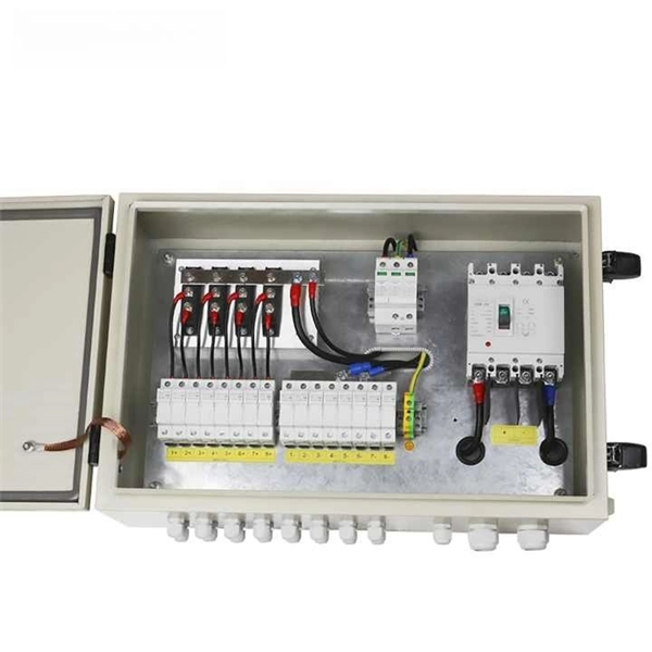
This handbook covers the code of practice in protection circuitry including standard lead and device numbers, mode of connections at terminal strips, colour codes in multicore cables, dos and donts in execution. Also principles of various protective relays and schemes including special protection. Read this document and the documents listed in the additional resources section about installation, configuration, and operation of this equipment before you install, configure, operate, or maintain this product. Users are required to familiarize themselves with installation and wiring instructions. presentation of protection and control relaying. The report will identify methodology behind these practices, present issues raised by the integration of microprocessor relays and the internal logic and external communication configurations, ying. The objective of this presentation is to convey a basic understanding of protective relays to an audience of engineers already familiar with low voltage protective device coordination. HT panel protection relay. The HT power supply is received from GO switch and distributed to the. The handbook for protection engineers includes guidelines on protective circuitry, protective relay principles, and testing procedures for switchgear and relays. It covers standard codes, wiring practices, and norms for protecting generators, transformers, and lines, and provides detailed.
[PDF]

87N high-impedance protection requires special class × current transformer cores with equal transformation ratios. The 7SJ60 relay can alternatively be connected in series with the 7UT613 relay to save this CT core. Earth faults on the secondary side are detected by current relay 51N. However, it has to be time-graded against downstream feeder protection relays. Primary circuit-breaker and relay may be replaced by fuses. Go back to contents ↑. Relay 7UT612provides numerical ratio and vector group adaptation. Matching transformers as used with traditional relays are therefore no longer applicable. Line CTs are to be connected to separate stabilizing inputs of the differential relay 87T in order to ensure stability in the event of line through-fault currents. Relay 7UT613provides numerical ratio and vector group adaptation. Go back to contents ↑. The directional functions 67 and 67N do not apply for cases where the transformers are equipped with the transformer differential relays 87T. Go back to contents ↑.
[PDF]

While nonarmored fiber optic cables don't require grounding due to their nonconductive properties, grounding is crucial when using armored fiber optic cables. Therefore, it is important to build a lightning protection system for fiber optic cables. How to Protect Fiber Optic Cable From Lightning? The major purpose of lightning protection systems is to conduct the high current lightning discharges safely into the Earth/ground. There are two main lightning. Fiber optic cable transmits data as light through glass or plastic strands, which means the fiber core itself carries no electrical current and requires no grounding. However, this does not mean every fiber optic installation is exempt from grounding requirements. Lightning-induced surges can travel through power lines, telecommunication lines, or nearby metallic structures and pose a. There are two main lightning protection grounding solutions in fiber networks, namely intermediate grounding and terminal grounding. These solutions use two ways of grounding for optical cable links both in domestic and foreign standards. However, because fiber optic cable has strengthened core, especially the direct-buried fiber optic cable has armoring layer.
[PDF]

Cable trays play a key part in keeping fire protection systems working. Here is what they do: They Make Safe Paths for Fire System Wires Cable trays are made from materials that resist fire. They can help stop fire from spreading. Recognize electrical cable tray misuse that can lead to electric shock and arc-flash/blast events and fires caused by overheating. The use and installation of cable trays is covered by legally enforceable OSHA regulations in 29 CFR 1910. 305(a)(3), or comparable standards promulgated by States. Scope: Firestopping for busway, cable trays, cables, and trunking passing through walls in enclosed electrical installations. Where cables pass through shafts, walls, slabs, or enter electrical panels or cabinets, openings shall be tightly sealed with firestopping materials in accordance with. Cable trays can be part of a planned cable management system to support, route, protect, and provide a pathway for cable systems. Power, low voltage control, data, or telecommunications wiring distribution systems can be used with cable trays. 1 This section applies to cable trays utilized to support and route low voltage cables (telecom, security, A/V). No fire alarm cables will be permitted to be installed in cable trays. If a fire starts, the tray protects the wires inside from flames and.
[PDF]

This guide covers everything: what fiber optic pigtails are, how they differ from patch cords, which connector and polish type to specify, how to choose between mechanical and fusion splicing, and the real-world applications where pigtails are the right call. Types and Applications A pigtail connector is a short cable with a connector on one end and bare (stripped) wire or fiber on the other. In fiber optics, pigtails are fusion-spliced to field fiber inside splice trays — the most common termination method in telecom and data center networks. In. Whether it's an electrical system in your car, home, or factory, the quality of the connection is essential, and that's where pigtail connectors come in. These small, often overlooked components ensure a strong, safe electrical connection. It serves as a bridge, allowing technicians to repair specific connection points without disturbing the rest of the system. By the end, you will have a comprehensive understanding of why pigtails deserve a place in every fiber deployment toolkit. People often make this connection in the field, where they must make temporary repairs or. Executive Summary: A fiber optic pigtail is one of the most commonly specified yet least understood components in structured cabling. Get the wrong connector type, the wrong polish, or skip proper fusion splicing technique—and you're looking at elevated signal loss, increased back reflection, and a.
[PDF]
A spectrometer is a scientific instrument used to separate and measure components of a physical phenomenon. Spectrometer is a broad term often used to describe instruments that measure a continuous variable of a phenomenon where the spectral components are somehow mixed. In a spectrometer can separate white and measure individual narrow bands of color, called a spectrum. A.
[PDF]

While traditional fiber optic cables contain individual fibers encased in a protective jacket, ribbon fiber cables organize fiber optic strands in a flat ribbon structure, creating freedom with space conservation and cable management. Data Centers: The flexible ribbon cables deliver phenomenal bandwidth between densely packed servers and networking gear in data centers. Motor Meter: Ribbon cables can be used to connect the control circuitry to the display or to the motor drivers. Telecom Devices: In telecommunications, flat. Ribbon cables offer higher fiber counts and greater fiber density than any other cable construction designed for the outside plant (OSP), four times the highest-fiber-count loose tube cable. Ribbon cables also enable mass-fusion splicing, whereby each 12-fiber ribbon can be spliced in a single. The technology of ribbon fiber optic cables is well-established in the telecommunications industry and is favored for its high fiber density and compact size. Join us as we embark on a journey of discovery, demystifying the technology that has changed the way we connect and communicate. Welcome to the world of Ribbon Fiber Optic Cables. One of our most innovative technologies is the ribbon fiber optic cable —a compact, powerful solution that is transforming the way organizations manage high-density connections while optimizing valuable space. In this article, we'll delve into why ribbon fiber optic cables are a game-changer, how.
[PDF]
Fiber optic couplers can either be passive or active devices. Passivefiber optic couplers are said to be passive as no power is required for operation. They are simple fiber optic components that are used to re.
[PDF]
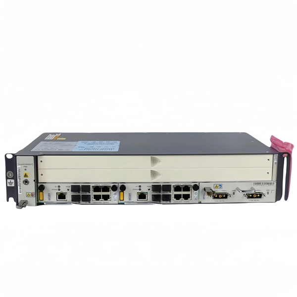
Includes dual power supplies, hot-swappable modules, link aggregation (LAG), and support for HSRP/VRRP. Modular chassis or stackable designs make it easy to scale as your network grows. 1X support, SNMP, CLI/Web GUI, and network access control. There are different types of enterprise switches that perform various roles in these layer-based or hierarchical ethernet networks. This white paper introduces the following three types of network switches and further discusses the selection criteria for each switch. What is a network switch? So, what is a network switch? A network switch is a vital component of a computer network that. What is Spanning Tree Protocol (STP) and why is it important in core switch networks? Can I use a cloud-managed core switch? How does Quality of Service (QoS) impact core switch performance? What Is a Core Switch in Networking? Understanding the Backbone of Your Network A core switch in networking. Providing The Most Competitive Networking Products For Global Customers! In the realm of system networking, three key types of switches are frequently mentioned: access switches, aggregation switches, and core switches. The part of the network that directly connects to user devices is referred to. What Is a Core Switch? The Definitive Guide to Network Architecture A core switch is a high-capacity, high-performance Layer 3 switch positioned at the physical backbone of an enterprise network. This post mainly explores the confusing problem: core.
[PDF]

Fiber optic connectors can be categorized according to different standards such as utilization, fiber count, fiber mode, and transmission method. They are also divided into single-mode and multimode types based on their distinct characteristics. This guide will walk you through the most common fiber connector types, explaining their characteristics, advantages, and typical use cases. Whether you're planning an FTTH deployment, upgrading a data center, or working in telecom infrastructure, this guide will help you make informed decisions. Compared to Copper cables, Fiber connector types are incredibly varied. Where copper twisted pairs tend to terminate with an RJ45 plug, fiber optic connectors come in all sorts of shapes and sizes, with all manner of different use cases in mind. An optical fiber connector is used to join optical. With a wide variety of connector types available, choosing the right connector for your network can be challenging. Learn how each connector works, where it's used, and how to choose the right option for today's high-density, high-speed networks. It is a precise coupling device that joins fiber optic cables quickly, enabling faster connection and disconnection than splicing. The connector mechanically orients the fiber cores, allowing light to pass and travel through. In this guide, you'll explore various types of fiber optic cable connectors, each with unique features and best uses. We'll also provide practical advice.
[PDF]