The fusion method fuses the fiber cores together with less attenuation. Fusion splicing stands out as a superior technique for joining optical fibers, offering a seamless, low-loss connection that is crucial for reliable fiber optic networks. Thorlabs offers a varied selection of single mode (SM), polarization-maintaining (PM), multimode (MM), and double-clad fiber couplers, as well as 1x8 and 1x16 SM PLC splitters; 1x4, 1x8, and 1x16 PM PLC splitters; wideband multimode circulators; RGB combiners; and WDMs. Our SM and double-clad fiber. Castor's Multimode Fiber Splitters (MFS) are designed to efficiently split or combine multimode signals with minimal insertion loss. Manufactured with step-index fibers with core diameter ranging from 50 to 400 µm, they offer uniform splitting ratios across output channels. This method provides a simple, rugged, and compact method of splitting and combining optical signals. Let's explore the fundamentals of mechanical and fusion. A fiber optical coupler (splitter/combiner) route signals to their appropriate destination by splitting, combining or tapping optical signals/channels in a fiber transmission link. Employing a unique fiber fusing process, Lfiber is now able to fabricate and offer a wide variety of fiber optic. Fused couplers are ideal components to split or combine light signals between two fibers over a wide wavelength and temperature range.
[PDF]
Single mode fiber patch cord: Single mode 9/125um optic patch cord are designed for long-distance transmission. They have a smaller core diameter (typically 9 microns) compared to multimodeoptic.
[PDF]

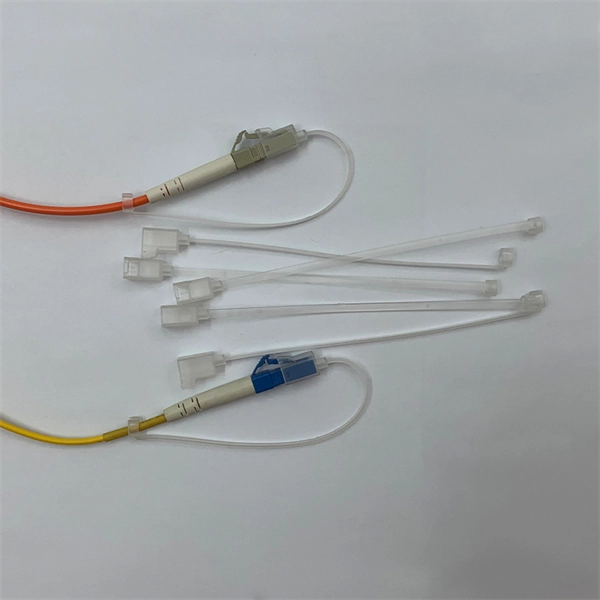
Since the earliest days of fiber optics, multimode cables have typically been color‑coded orange, black, or gray, while single‑mode cables are marked in yellow. For example, cable jacket color typically defines the fiber type, and can differ based on mode and performance level. These colors are typically chosen by industry standards bodies. However, there are some non-standardized colors and inconsistencies that you should be aware of. However, with the introduction of metallic connectors like FC and ST—whose bodies are difficult to color‑code—colored strain relief boots. Multimode fiber (MMF) is a kind of optical fiber mostly used in communication over short distances, for example, inside a building or for the campus. Multimode fiber optic cable has a larger core, typically 50 or 62. 5 microns that enables multiple light modes to be propagated. Because of this, more. Originally developed by the Electronic Industries Alliance (EIA) and the Telecommunications Industry Association (TIA), the TIA-598-D standard (formerly EIA/TIA-598) remains the most recognized color-coding system for optical fibers worldwide. On the right, the yellow patchcord indicates singlemode fiber and the blue connector means it is a regular PC polished connector, If it were an APC connector, it would be green. Perhaps nothing is.
[PDF]
While most Rayleigh based fiber sensors use single mode fiber, multimode fiber has the potential to provide lower noise due to the higher capture fraction of Rayleigh scattered light, higher non-linear thresholds, and the ability to avoid signal fading by measuring many. While most Rayleigh based fiber sensors use single mode fiber, multimode fiber has the potential to provide lower noise due to the higher capture fraction of Rayleigh scattered light, higher non-linear thresholds, and the ability to avoid signal fading by measuring many. Speckle imaging through single multimode fibers (MMFs) has garnered significant attention for its minimally invasive nature and high imaging resolution. However, the prevalent fully serial sampling approach severely limits imaging speed. A convolutional neural network is utilized to establish the mapping relationship between speckle and Stokes parameters. The lowest root-mean-square error of the estimated SOP on the.
[PDF]
Optical fiber is composed of three elements – the core, the cladding and the coating. These elements carry data by way of infrared light, thus propagating signal through the fiber. The core is at the center of the optical fiber and provides a pathway for light to travel. A TOSLINK optical fiber cable with a clear jacket. These cables are used mainly for digital audio connections between devices. A fiber-optic cable, also known as an optical-fiber cable, is an assembly similar to an electrical cable but containing one or more optical fibers that are used to carry. This is the first in a series of five courses about fiber optic cable systems. The first course, Fiber Optics I –Theory, is an overview of the technology of fiber optic. An optical fiber cable is a complex structure designed to protect fragile glass fibers that transmit digital data using light signals. This advanced cabling solution allows fast, secure data transfer and telecom over long distances. When searching for a fiber optic cable, we need to pay attention not only to the connectors, such as SC to ST fiber cable, LC to SC fiber patch cable, or SC to. This guide explains the structure of fiber optic cables, the most common cable constructions used in the industry, and how to choose the right cable type for indoor networks, outdoor deployments, data centers, and FTTH systems. In multimode fiber, the.
[PDF]

This is where a small but mighty hero comes into play: the Mode Conditioning Patch Cable (MCP). In this guide, we'll demystify what a mode conditioning patch cable is, why it's essential in specific network scenarios, and how it can save you from a world of connectivity headaches. This guide offers the key technical insights you need to select and install the optimal fiber optic cabling solutions for your specific needs. Covers the basics of fiber optic technology, including how light waves transmit data through thin strands of glass or plastic, and why fiber optics surpass. Fiber optic cables use light to transmit data, whereas traditional cables rely on electrical signals, which are more prone to interference and loss over distance. Connector types play a crucial. Fiber optic technology has transformed the way we transmit data, enabling faster, more reliable connections than traditional copper cables. Understanding fiber optic cable types is essential for anyone looking to build or maintain efficient fiber networks. We'll also. This is a plain-English guide for facilities and IT teams who want fiber that performs well, stays organized, and doesn't turn every add/change into a disruption. Start with the link's distance and speed, then pick single-mode (OS) or multimode (OM)—not the other way around.
[PDF]

In fiber-optic communication, a single-mode optical fiber, also known as fundamental- or mono-mode, is an optical fiber designed to carry only a single mode of light - the transverse mode. Modes are the possible solutions of the Helmholtz equation for waves, which is obtained by combining. Single-mode fiber is a specialized type of optical fiber designed to transmit light along a single, narrow path, or “mode. ” This technology is foundational to modern digital communication, enabling the high-speed transfer of massive amounts of data over vast distances. This type of fiber is used for transmitting signals over long distances. It is specified as the best for especially long-distance applications than multimode fiber. This saves space and money. Dual fiber modules use two fibers. They are easier to set up and give steady communication. It comprises one glass or plastic fiber and features a tiny core of about 8-10 microns in diameter. This. There are two main types of fiber optic cables: single mode and multimode. Although they can do the same job in some instances, the different construction methods make each of them better suited to certain tasks and budgets.
[PDF]

By operating from a single 2. 5V input power rail and integrating the controller, gate driver, power inductor, and MOSFETs, these mini modules are optimized for space-constrained applications like optical modules, wearables, IoT, networking. SFP (Small Form-factor Pluggable) optical modules are compact, hot-pluggable transceivers that enable network equipment to connect seamlessly to fiber and copper links. These modules, including SFP, SFP+, and SFP28, are widely used in enterprise networks, data centers, and carrier-grade deployments. The optical module serves as a crucial component in optical fiber communication systems, operating at the physical layer, which is the lowest layer in the OSI model. Its primary function is to achieve optoelectronic conversion by converting electrical signals into optical signals and vice versa. Think of it as the “translator” for your network equipment, converting electrical signals into optical signals. As an essential component of optical fiber communication, optical modules are optoelectronic devices that facilitate the conversion between optical and electrical signals during the transmission process. They are essential in applications like telecommunications, data centers, and enterprise networks. Optoelectronic devices have transmitting and receiving modes.
[PDF]

While most pigtails are single-fiber, multi-fiber options exist: Single-fiber: The most common (LC, SC, FC). Multi-fiber: 2, 4, 6, 12, 24, 48, or 72 fibers. Multi-fiber pigtails often come in ribbon format for splicing into high-count cables. Traditional Fusion Splice-On Connectors with pigtails provide factory-polished performance with field-termination convenience within harsh environments. Mass fusion splicing can fuse up to all 12 fibers in one ribbon at once. Mass Fusion Pigtails come with all 12 fibers terminated and a ribbonized. By fiber type, there are single-mode fiber optic pigtail and multimode fiber optic pigtail. And by fiber count, 6 fibers, 12 fibers optic pigtails can be found in the market. Fiber pigtails are used in an estimated 99% of single-mode fiber applications worldwide. Despite this ubiquity, they remain a source of confusion for procurement teams and junior installers alike—especially when it comes to connector type selection, polish type, and the tradeoffs between mechanical. Fiber optic pigtails can be divided into single-mode and multimode fibers. Conversely, multimode fiber pigtails, usually orange, use a 62. 5m to 2m—that has a factory-terminated connector on one end and bare fiber on the other end. The connector end is polished and tested under factory conditions, ensuring low insertion loss and high return loss.
[PDF]
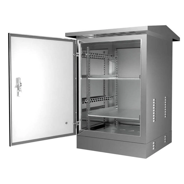
It integrates fiber splicing, splitting, distribution, storage, and cable connection into one unit, providing solid protection and efficient management for building reliable FTTX networks. Total Enclosed Structure: Ensures maximum protection. This fiber optic distribution box serves as a termination point for feeder cables to connect with drop cables in FTTX communication network systems. It is. An optical distribution frame (ODF) is a frame used to provide cable interconnections between communication facilities, which can integrate fiber splicing, fiber termination, fiber optic adapters & connectors and cable connections together in a single unit. It can also work as a protective device. A Fiber Optic Termination Box is a small enclosure located at the terminal end of the fiber where it enters your customer premises. Its function is primarily to splice, secure, and protect the optical fibers connecting the incoming drop cable to the pigtail or patch cable. We separate these products into multiple groups based on application to meet your specifications for mount location and termination capacity.
[PDF]

Not all splitters are created equal. Here are the main types you'll encounter: The "1×N" notation indicates one input fiber and N output fibers. A 1×2 splitter divides the signal into two outputs, while a 1×8 splitter divides it into eight. The more splits, the. By dividing a single optical signal from a central Optical Line Terminal (OLT) into multiple outputs for Optical Network Terminals (ONTs) at users' homes, splitters eliminate the need for dedicated fibers to each residence—slashing infrastructure costs while scaling network reach. This guide. A fiber-optic splitter, also known as a beam splitter, is based on a quartz substrate of an integrated waveguide optical power distribution device, similar to a coaxial cable transmission system. The optical network system uses an optical signal coupled to the branch distribution. The fiber optic. Optical couplers can split or join signals in fibers. You can connect many users to one port with 1:n or 2:n splitters. These devices work both ways, which helps strong network communication. In a Passive Optical Network (PON), a single optical fiber carries massive amounts of data using light. They are named by the number of inputs and outputs, so a splitter with one input and 2 outputs is a 1X2, and a PON splitter with one input and 32 outputs is a 1X32.
[PDF]

A single strand of glass fiber, called single-mode fiber, is used to transmit single-mode or light beams. It can transmit higher bandwidth than multimode fiber but requires a light source with a limited spectral range. There are mainly two types of optical fibers, single-mode optical fiber, and multimode optical fiber, which differ in the way light propagates. The latter is used for short-distance transmission, while the former is typically used for long-distance signal transmission. Please refer to the article. Single fiber modules (BiDi) use one fiber for both transmitting and receiving data. This saves space and money. Dual fiber modules use two fibers. They are easier to set up and give steady communication. Single-mode optical modules are best for long distances and fast speeds. Modes are the possible solutions of the Helmholtz equation for waves, which is obtained by combining. Optical fiber transmission is based on the principle of total internal reflection, where light signals are transmitted through a thin glass or plastic fiber with a core and cladding. The core has a higher refractive index than the cladding, causing the light signal to be reflected back into the. OS1 single mode fiber optic cables are made with a single mode fiber core, which means that they have a very small core diameter of 9 microns. Each type serves distinct applications based on its light transmission characteristics. Very small core (~8–10 µm). Carries one light path (mode).
[PDF]

The complete process for terminating cable runs at a patch panel, from mounting and cable management to punch-down, labeling, and testing every port. To wire a patch panel: Mount the panel in your rack. If you're still deciding which panel style fits your site (keystone vs punch‑down vs pass‑through), start with How to choose a patch panel and come back here once the hardware is locked in. 60-second answer If you want reliable results, the winning recipe is simple: keep pair twists tight right up. Network patch panel, cable manager, network cable, wire stripper, crimping tool, zip ties. Use a small yellow tool or wire stripper to remove the outer jacket of the network cable. Cut off the cross-shaped skeleton of the Cat6 patch cord. Insert. Patch panels make cable management and network organization very easy over long periods of time, but you'll need to wire the panels in order to put them into your network. Not to worry, this guide will walk you through the whole process. Before you jump into the task, ensure that you have the. Testing a patch panel is an essential task to ensure the reliability and efficiency of a network infrastructure. The process verifies the end-to-end connection, ensuring the cable is properly terminated at the wall jack and at the distribution point, such as a switch or patch panel.
[PDF]
Based on the requirement of relevant standards, this paper discusses automatic testing exploratory research, by analyzing the principal experimental objects and information transmission mode of the distribution automation terminal, which adopts IEC-60870-5-104 protocol. The Distribution Terminal Unit (DTU) is a core terminal device designed specifically for modern smart distribution networks. Essentially, it is an intelligent device that integrates data collection, processing, transmission, and control functions. As an important component of the distribution. In this paper, the intelligent industrial automatic technology is used to detect the malfunction indicators and distribution terminals to improve detection efficiency. The system is. This article introduces a case of 35kV ring main unit busbar insulation breakdown failure, analyzes the failure causes and proposes solutions , providing reference for the construction and operation of new energy power stations. On this basis, this paper. Distribution Automation Terminals are an important part of distribution automation systems to deliver real-time monitoring, fault detection, fault location, isolation and power restoration in non-fault areas on multi-line systems. The tester host includes a tester slot in which a USB type wireless network module is inserted. The tester host conducts data.
[PDF]

Mixing singlemode and multimode pigtails in the same link is a common and costly mistake. The core diameters (9 µm vs. 5 µm) are fundamentally incompatible—attempting to splice or connect them results in massive insertion loss (often 10+ dB) that will fail every optical power. Fiber optic pigtails play a critical role in modern optical networks, serving as the interface between optical fibers and active or passive devices through fusion splicing. Among the various options available, singlemode fiber pigtails and multimode fiber pigtails are the two most widely used. Choosing between single-mode and multimode fiber optic pigtails is one of the most important decisions in network design. These differences determine which transceivers work with which fiber and how far signals can travel. Understanding the compatibility constraints prevents costly downtime and troubleshooting. Choosing the right pigtail directly impacts signal transmission distance. So what's the cause of mix-using multimode and single-mode fiber? As we see, the optics applied in point-to-point interconnection are symmetrical. For instance, end A with a 10G SFP+ port houses a 10GBASE-SR SFP+ module.
[PDF]