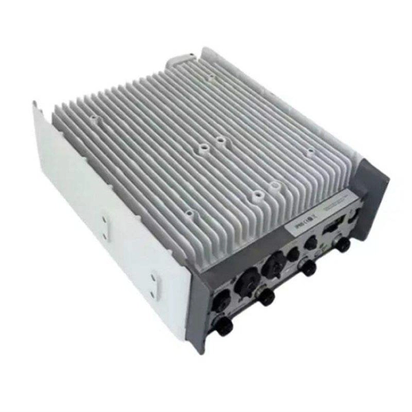
An optical line termination (OLT), also called an optical line terminal, is a device which serves as the service provider endpoint of a. It provides two main functions: 1. to perform conversion between the electrical signals used by the service provider's equipment and the signals used by the passive optical network.
[PDF]
Optical line terminals, also called optical line terminations (OLTs), serve as endpoints for passive optical networks (PONs). They convert electrical signals from equipment managed by a service provider to fiber optic signals readable by a PON. It provides two main functions: to perform conversion between the electrical signals used by the service provider's equipment and the. In the age of fiber-to-the-home (FTTH) and ultra-broadband connectivity, the Optical Line Terminal - or OLT - is one of the most crucial devices powering our high-speed digital world. When you stream a 4K video, join a remote meeting, or play an online game on a gigabit fiber connection, an OLT. At the heart of a point-to-multi-point or passive optical network (PON) is the optical line terminal (OLT). Modern OLTs offer communication service providers (CSP) the ability to launch multigigabit services to tens of thousands of subscribers from a single location or just ten. Whether you are using high-speed internet at home, watching IPTV, or running cloud-based.
[PDF]

The 6 terminal junction box wiring diagram provides a visual representation of how the various wires and connections should be made within the box. It shows the layout and arrangement of the terminals, as well as the color coding and labeling of the wires. Hey, in this article we are going to see the Single Phase Distribution Box Wiring Diagram and Connection Procedure. A distribution board or distribution box is where the main power supply is distributed to multiple loads. It provides a quick and easy reference guide to understanding the meaning behind each symbol. These symbols can represent different electrical components, such as switches, resistors. This technical article aims to take you on a journey through the fundamental terminals and other connecting elements of wiring diagrams and electrical schematics and to delve into the minute intricacies of the components that form them. From the familiar male and female terminals that form the. An electrical panel box, also known as a breaker box or a distribution board, is a crucial component of any electrical system. Whether you're an electrician or a DIY enthusiast, this guide will help you understand the basics of home electrical distribution. more Welcome to our. The Engineering Base terminal block diagram is a special template showing information about terminal blocks, terminals and their accessories. There are two methods for creating a terminal block.
[PDF]
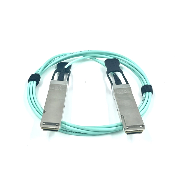
If you encounter any of these issues, check the optical connector for damage or dirt, inspect the fiber optic patch cord, ensure the optical module is correctly installed, and check the device settings for compatibility. Subsequently, the driver semiconductor laser (LD) or light-emitting diode (LED) emits modulated optical signals at the corresponding rate. After transmission through the optical fiber, the receiving interface converts the optical signals into electrical signals using a photodetector diode and. An optical module is a typically hot-pluggable optical transceiver used in high-bandwidth data communications applications. Optical modules typically have an electrical interface on the side that connects to the inside of the system and an optical interface on the side that connects to the outside. The Transmitter Optical Sub Assembly (TOSA) is responsible for the emission of light. Its primary function entails converting electrical signals into optical signals.
[PDF]

Check the electrical load and ensure that the sensors do not exceed the 10 Amp maximum. Check each wire for damage that may lead to a short. Check the tightness of electrical connections along the power supply. Each powernet distribution box (PNDB) on the vehicle provides up to 4 low amperage circuits (30 amp and less), and up to three high amperage circuits through midi fuses. The fuses are located behind a cover on the face of the PNDB. On vehicles equipped with a cab load disconnect switch (CLDS), the. These limits are designed to provide reasonable protection against harmful interference when the equipment is operated in a commercial environment. This equipment generates, uses and can radiate radio frequency energy and, if not installed a nd used in accordance with the instruction manual, may. I currently dont have any power to the distribution box. For some reason, I cant find the issue why there is no power into the distribution box. The wire that is attached to the box near the fender, does have power. Here are some solutions when a power distribution box fails: Safety First: Make sure you are safe. However, in actual applications, distribution boxes often encounter a series of problems, which not.
[PDF]
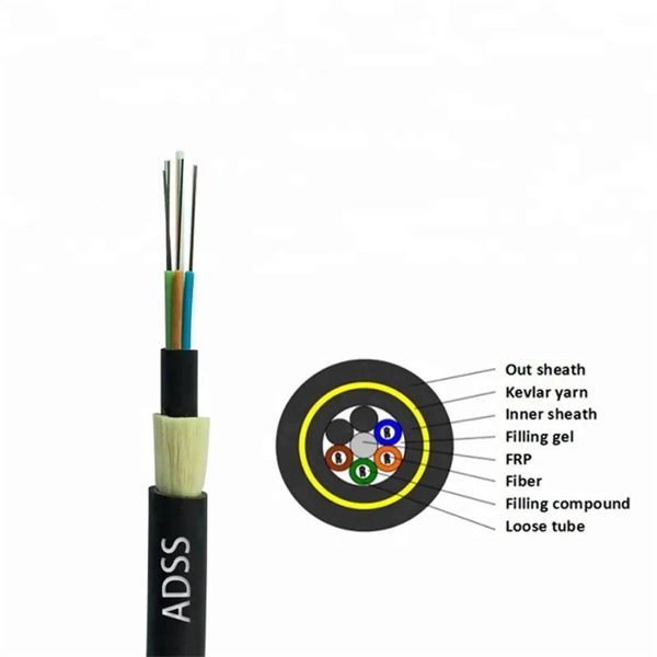
For high intracavity powers (e. tens of watts), however, detrimental thermal effects can occur, such as a shift of the reflection band and a decrease of reflectance. For not too high power levels, volume Bragg gratings can also be used in spectral beam combining. There are fiber Bragg gratings. An optical fiber grating is a small segment within an optical fiber altered to act as a selective filter for light. This treated area functions like a specialized mirror, reflecting a specific wavelength of light while allowing all other wavelengths to pass through. This microscopic structure. Optical fiber grating technology serves as a foundational stone in modern communication and sensing systems. This technology relies on periodic structures within optical fibers that modify the propagation of light, enabling a myriad of applications ranging from telecommunications to environmental. Fiber Bragg grating (FBG) sensors have emerged as advanced tools for monitoring a wide range of physical parameters in various fields, including structural health, aerospace, biochemical, and environmental applications. This review provides a comprehensive overview of FBG sensor technology. A fiber Bragg grating (FBG) is a type of distributed Bragg reflector constructed in a short segment of optical fiber that reflects particular wavelengths of light and transmits all others. This can be achieved by making use of fiber photosensitivity. At each interface between two regions.
[PDF]
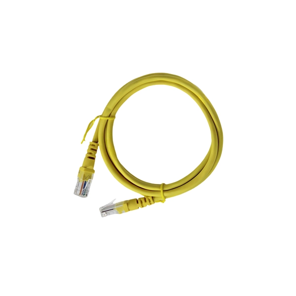
Fiber optic patch cords do not have “polarity” in the sense of electrical positive and negative terminals, like a battery. Plugging them in “backwards” will not cause a short circuit, and it will not burn out or damage your equipment. Patch cord polarity defines the directional optical path between two transceivers, ensuring that the transmit (Tx) signal from one device reaches the receive (Rx) port of the other. Patch cables for fiber optic can have the same connector on each end (e. Since fiber optic links require a two-way - or duplex - connection, there is potential for errors in installation by connecting transmitter to transmitter or. As networks move to higher speeds and higher density, choosing the right fiber optic patch cords becomes critical to the reliability of your system. At ZION Communication, we design and manufacture a full range of fiber patch cords for: This guide will help you quickly understand the main types of. Negative poles have a greater number of electrons relative to positive poles; when connected, electric current will flow from negative to positive. When used in the context of fiber-optic communication, this is analogous to the flow of data in the form of light signals from transmit (Tx) to receive. Simplex optics: A single fiber is used to plug things in and establish transmit and receive one one fiber in one direction. Parallel optics: Multiple fibers used to establish higher.
[PDF]
An optical line termination (OLT), also called an optical line terminal, is a device which serves as the service provider endpoint of a passive optical network. It provides two main functions: to perform conversion between the electrical signals used by the service provider's equipment and the fiber optic signals used by the passive optical network.to coordinate the multiplexing between the conversion. FeaturesOLTs include the following features: • A downstream frame processing means for receiving and churning an cell to generate a downstream frame, and converting a parallel dat. Most vendors integrate an entire fiber optic management system for ISPs to manage OLTs as well as client ONTs and as such are not interoperable. • • BT-PON.
[PDF]