Unplug the electrical power cord of your BBU from the wall outlet. Open the battery cabinet on the BBU (you may need a screwdriver to do this). So, what DOES work for keeping track of your battery status? The right solution will help you solve the problems above without dooming you to the pitfalls above. Monitors the "Big 3" elements of battery health: voltage, temperature, and internal resistance. Provides 7x24x365 protection - without. This paper describes a step by step program of methods and procedures for maintaining the VRLA battery systems in the Local Exchange Carrier Central Office and Outside Plant Telecommunication Cabinet environments. Embracing these methods and procedures allows the user to obtain maintenance and test. Proper sizing of a telecom battery bank is essential for ensuring reliable power delivery and optimal performance. By calculating your energy needs and understanding the technical aspects of battery configurations, you can build a system that meets your requirements effectively. To size your. The DC Battery Module is a component of the DC power distribution panel for telecommunications that ensures the batteries fulfill. By understanding the methods for calculating battery capacity, charge/discharge rates, and cycle life, you can optimize the performance of your telecom cabinet power system and telecom batteries. Ensure the area is free from dust and vibrations, as these factors can affect the.
[PDF]

Step-by-step guide on connecting an inverter to your distribution board for uninterrupted power supply. The process begins with turning off the main power supply to ensure safety. Next, choose an inverter with a suitable capacity to handle your power needs, ensuring it matches the. In this article, you will find information about connecting inverter to distribution box: essential safety tips, step-by-step guidance, and common mistakes that often lead to inverter failure, so that you can avoid them. Last Updated on September 17, 2025 by June The most extensive use of inverter. Connecting an inverter to a distribution board allows you to harness stored energy from batteries or solar panels for powering electrical devices in your home. This setup provides backup power during outages and can also contribute to energy savings by utilizing renewable energy sources. This guide. In this video, we'll guide you through the process of wiring a UPS (Uninterruptible Power Supply) or inverter for your home or office. By following a few simple steps, you can easily learn how to connect an inverter DB wiring diagram. Connecting an inverter DB wiring. Scroll to the bottom of any page to find a sun or moon icon to turn dark mode on or off! I'm not an electrician and do not want to screw this up. What type of wiring do I need to connect the inverter to the distribution box? I have a 1*60A 4*20A FL+LS distribution box with a Sungold Power 5000W 48V.
[PDF]

This manual describes the protection, automation, control, and monitoring functions of the SIPROTEC 5 devices. In order to protect technical infrastructures, systems, machines and networks against cyber threats, it is necessary to implement – and continuously maintain – a holistic, state-of-the-art. Busbar Differential Protection Definition: Busbar differential protection is a scheme that quickly isolates faults by comparing currents entering and leaving the busbar using Kirchoff's current law. Current Differential Protection: This protection method connects CT secondaries in parallel and. A busbar protection is a protection to protect busbars at short-circuits and earth-faults. In the “childhood” of electricity no separate protection was used for the busbars. With increasing short-circuit power in the network. SIPROTEC 7SS60 7SS60 is a numerical differential current protection for busbars. It is suitable for all voltage levels and can be adapted to a large variety of busbar configurations. Busbar protection is critical for the safe and reliable operation of a power system. Related Article: Busbar Protection Like any other faults. Bus bar protection scheme shall be provided for 220KV system where the sub-station layout arrangement is with 3-bus system (Main 1, Main 2 & Transfer Bus) or two bus system with Main bus with bus section breaker & Transfer bus.
[PDF]

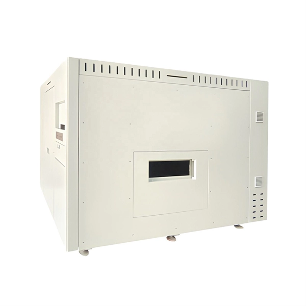
The compact 1 port ftth fiber termination box can hold 2 cores splicing, termination and coil up to 30 meters long for cable management in FTTH network. The 1 port fiber termination box is available for fiber optic cable coiling, it is great to connect optical cable and pigtail and protect fiber splices from damage. It is small, lightweight, and offers the function of fiber splicing, storage, and termination, mainly used in residential buildings. The maximum distance for single mode fiber optic cable can extend up to several hundred kilometers, making it ideal for long distance data transmission. One type of single mode fiber is known as “G. 652,” which is commonly used in telecommunications networks. Here are some general guidelines: 1. The shorter distance accounts for the. A fiber optic distribution box (FDB) is a protective enclosure for managing fiber optic cables. It organizes connections, splices fibers, and distributes signals in networks like FTTH (Fiber-to-the-Home) or FTTB (Fiber-to-the-Building). It acts as a central point for terminating, splicing, and distributing these cables, providing necessary protection and. The Fiber Optic Association, Inc. (FOA) was founded in 1995 to help develop the workforce to build the fiber optic networks to support a rapid expansion in communications and the Internet. The charter of the FOA was to promote professionalism in fiber optics through education, certification, and.
[PDF]

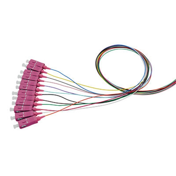
Basic — 1,000 ft single-mode run indoors with minimal termination: Cable $0. 00/ft, Permits $150, Accessories $100. Total ≈ $2,650–$3,100. 60/ft . Free Shipping with $189 Order. 100% Satisfaction Guaranteed. 30-Day Return Warranty Technical Support Live Chat. Pre-terminated Fiber Optic Cable is a hassle-free and reliable solution for realizing fiber connection without huge investment and complicated termination. Simply plug the cable to any. When you buy cables pre-terminated from Discount-Low-Voltage. com, you'll get value pricing and reliable performance. Our pre-terminated fiber optic cables save you the trouble and expense of terminating cables on site, expediting installations and reducing labor costs. 36dB/1000m ² Insertion Loss (1550nm wavelength) for pre-terminated butterfly drop cable with L > 200m: 0. They ensure the efficient delivery of audio, video, data, fiber internet, smart controls, and support HDMI. FS offers pre-terminated multifiber optic cable assemblies at wholesale price that save much installation costs and times for indoor/outdoor fiber optic cabling systems. Buyers typically pay for fiber optic cable by length, fiber type, and installation complexity. This guide presents ranges in USD and practical price estimates to help.
[PDF]
We're talking anywhere from $45 for a small residential unit to over $6,000 for industrial-grade modules. In this guide, as a professional hollow fiber membrane manufacturer, I'll break down exactly what influences these prices and how to get the best value for your specific. What's the hollow fiber membrane price going to set you back? Here's the deal: Hollow fiber membrane costs vary WILDLY. The Global Hollow Core Fiber Market will grow at a CAGR of 10. 92% from 2025 to 2031, reaching USD 24. Industrial uses and innovation fuel this surge, with the market predicted at USD 11. The pricing dynamics of the hollow core fiber market are influenced by factors. Check each product page for other buying options. Price and other details may vary based on product size and color. Need help?. The price of hollow fibers varies significantly based on material composition, manufacturing process, sustainability, and performance characteristics. Understanding the different types helps buyers make informed decisions for both commercial and personal applications. Fibers colored during the. Cobetter hollow fiber filters are made of low-binding modified polyethersulfone membranes (m-PES) that deliver excellent filtration performance. The low shear stress makes it ideal for the processes of cell harvest, clarification, diafiltration and concentration where gentle and fast separation is.
[PDF]

In this tutorial, I will show you how you can connect the Optocoupler to Arduino, read the data as Analog or Digital, and if necessary convert the analog values to digital, and how to reduce noise from the sensor. The Infrared Slotted Optical Optocoupler Module is a device that uses infrared light to transmit signals between two electrically isolated circuits. It consists of an infrared emitter (LED) and a photodetector (phototransistor) housed in a slotted enclosure. When an object passes through the slot. Slotted Optocouplers (Photo Interrupters) are very useful sensors, often included in Arduino projects to detect position of moving objects, measure speed of rotation, or linear motion, frequency of events, and many others. They are easy to use, but it is important to understand how they work, so. This tutorial is a comprehensive, practical guide to the Speed Sensor / Tacho Sensor (Slot-Type Optocoupler) (Leobot Product #245). Moreover, a simple application is programmed that shows how to wire and how to program an Arduino when working with the module. In this tutorial, the module is used as an “digital input board”. If you want to use the. In this project, I will talk about Phototransistor Optical Interrupter Switches (Opto Coupler) Module, how this module works and helps in determining the speed of a rotating object and finally I will show you how to Interface Optical Interrupter Switch Sensor with Arduino and measure the speed of a.
[PDF]

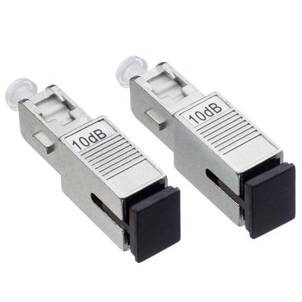
While optical power meters are the primary power measurement instrument, optical loss test sets (OLTSs) and optical time domain reflectometers (OTDRs) also measure power in testing loss. TIA standard test FOTP-95 covers the measurement of optical power. This measurement is the basis for loss measurements as well as the power from a source or presented at a receiver. Typically both transmitters and receivers have receptacles for fiber optic connectors, so measuring the. You need a power meter to measure power in a fiber optic system; most power meters come with a screw-on-adapter that matches the connector being tested and a little aid from the network electronics to turn on the transmitter. During the measurement of power, the meter must be set to the proper. Fluke Networks sets the standard in network testing with its advanced range of fiber optic power meters and fault locators, designed to ensure the highest precision in fiber optic meter readings and power evaluations. This is measured in decibels (dB). Splitters, fusion splices, connectors and. To use a power meter for fiber optic testing, always clean connectors first with lint-free wipes or click-to-clean tools. Select the correct wavelength and set your reference. Consistent procedures ensure accuracy.
[PDF]

As fiber optic cables are generally only produced in lengths up to around 5 km, so when lengthier connections are needed, splicing two cables together becomes necessary. So in essence, fiber optic splicing is a process used to join two separate fiber optic cables together. There are numerous use cases for fiber optic splicing. As. The time it takes to splice a fiber optic cable can vary depending on several factors, including the type of splice, the equipment used, and the level of expertise of the technician performing the splice. Proper termination is essential for ensuring optimal performance, reducing signal loss, and maintaining the durability of the connection. Another method of connecting optical fibers is termination or connectorization, which consists of processing the end of a fiber optic bundle so that it can be connected to other fibers or devices through fiber optic. Fiber optic joints or terminations are made two ways: 1) splices which create a permanent joint between the two fibers or 2) connectors that mate two fibers to create a temporary joint and/or connect the fiber to a piece of network gear. Either joining method must have three primary characteristics.
[PDF]

Average Optical Power: How bright the light is (measured in dBm). Too dim? Your signal gets lost in the fiber. Extinction Ratio: The difference between “on” (1) and “off” (0) light power. A higher ratio = cleaner signals. Transmitter Side: An electrical signal hits a laser diode (LD) or LED, which spits out light. Receiver Side: Light enters a photodetector (like a tiny solar cell), which turns it back into electricity. A built-in amplifier boosts the signal for your. The average transmitted optical power refers to the optical power output by the light source at the transmitting end of the optical module under normal working conditions, which can be understood as the intensity of light. In communication, we usually use dBm to represent optical power. However, in practical use, we adopt the average Tx power. The transmission power is related to the. This article provides an in-depth analysis of two key performance indicators of optical modules: transmitter power and receiver sensitivity. Transmitter power characterizes the average optical power output from the laser under rated conditions, while receiver sensitivity indicates the minimum. An optical module is a connecting module that serves as an optical-electrical conversion device. At the receiver end, the optical signals are reconverted into electrical.
[PDF]

In this blog, we will explore the step-by-step process of using a beamsplitter cube effectively, along with some common applications that benefit from this powerful optical tool. Step-by-Step Guide on Using a Beamsplitter Cube. A beam splitter is an optical device that divides an incoming light beam into two separate beams. One beam is typically reflected while the other is transmitted. The ratio of reflected to transmitted light can vary based on the design of the beam splitter. Beam splitters typically come in the form of a reflective device that can split beams into exactly 50/50, half of the beam being transmitted through the splitter and half being reflected. It is a crucial part of many optical experimental and measurement systems, such as interferometers, also finding widespread application in fibre optic telecommunications. Sometimes it is referred to as a half-silvered mirror. Either way, it is a simple material that YOU could use right at home for cool DIY projects like. The beam splitter has played numerous roles in many aspects of optics. For example, in quantum information the beam splitter plays essential roles in teleportation, bell measure-ments, entanglement and in fundamental studies of the photon. Additionally, beamsplitters can be used in reverse to combine two different beams into a single one. Beamsplitters are often classified according to their construction: cube or plate.
[PDF]

Non-polarizing beamsplitters are specified by their splitting ratio, i. the ratio of P-polarized light to. A beam splitter or beamsplitter is an optical device that splits a beam of light into a transmitted and a reflected beam. It is a crucial part of many optical experimental and measurement systems, such as interferometers, also finding widespread application in fibre optic telecommunications. a laser beam) into two (or sometimes more) beams, which may or may not have the same optical power (radiant flux). Different types of beam splitters exist, as described in the. The collimated incident laser beam passes through the beam splitter, and the output beam is emitted at a specific separation angle on the output beam array. The following figure is an introduction to the basic settings of a beam splitter. Circular beamsplitters, plate beamsplitters and cube beamsplitters can be purchased for polarizing or non polarizing beamsplitting. Beamsplitters are optical components used to split incident light at a designated ratio into two separate beams.
[PDF]

Professional Cable Tray Elbow Making | Metal Fabrication Tutorial Learn how to make cable tray elbows professionally with step-by-step guidance. This video shows metal fabrication techniques, DIY cable tray projects, and tips for perfect bends and joints. Whether you are a DIY enthusiast. The method for producing bridge bend elbows is as follows: Take a 90-degree cable tray bend elbow as an example, and apply the same principles for 45-degree bends accordingly. The length of the bottom side (bottom diagonal) after bending the cable tray should be equal to the width of the cable. This manual is designed to guide workers through the detailed production process of ladder cable trays, including the manufacture of horizontal elbows, tees, crosses, reducing bends, and vertical bends, with emphasis on precision, safety, and quality control. What's Involved in Producing Ladder. The bends, tees, crosses, risers and reducers of wire mesh cable tray can be easily and quickly made live at the project by using a bolt cutter. Since the jaws of the bolt cutter drags a layer of zinc across the cut end and forms a protective layer. When a wire cable tray is cut, the fact that a. How to bend 22. 5 DEGREE OF CABLE TRAY 3 LA. How to bend 90 degree of cable tray 3 line with the same distance :// • HOW TO BEND 90 DEGREE OF CABLE TRAY 3 LINE. Enjoy the videos and music you love, upload original content, and share it all with friends, family, and the world on YouTube.
[PDF]
In this video we show you how to dismantle a concrete telecommunications tower with a crane truck. Every health and safety measures at work were strictly comp. PTTG has experienced crews available to help when owners determine they no longer need their tanks, towers, or other structures and require them to be dismantled and removed, including scrap disposal and site cleanup. On occasion, tanks or towers cease to function or become too old to maintain. This can include towers, batteries, internal equipment, hazardous material, and communication shelter removal. We handle each project with safety and sticking to a budget in mind. Cellular tower demolition jobs can be trickier than most jobs. Legalities of what third parties have access to the site can cause issues–issues we will take care of. Our experienced team handles all aspects of decommissioning, including: • Mount & Antenna Removal – Dismantling old equipment with precision. • Microwave Decommissioning – Safely uninstalling.
[PDF]
In this guide, I'm excited to share with you 15 creative and surprisingly simple ways to transform your ugly electrical box from an eyesore into a part of your home you might actually want to show off. There are actually a whole host of creative and, more importantly, stylish ways to conceal your breaker box or electrical panel without blocking access or impeding functionality. But before you get started, make sure you double-check with an electrician and your local codes. Some electrical codes. Either way, here are unique electrical panel cover ideas to give you some inspiration. Don't let an ugly gray metal electrical panel ruin your decor! Check out these creative solutions for covering one in any room (removable, of course). Our editors and experts handpick every product we feature. We may earn a commission from your purchases. Which is exactly where I was struggling, we have an electrical panel directly in our dining room (small space problems). These fellow bloggers turned their electric panel doors from eyesores into focal points and pieces of art.
[PDF]
