Simple 3-phase distribution board wiring diagram for home use, showing safe connection of power supply, breakers, neutral, and earth for residential electrical systems. Hey, in this article we are going to see the Three (3) Phase Distribution Board Wiring Diagram and Connection Procedure. The three-phase distribution board is used to distribute power to the three-phase loads and circuits such as three-phase motors, three-phase machinery, three-phase to. A distribution board, also known as a DB box, is like the central hub of an electrical system. It contains multiple circuit breakers and connects various electrical circuits to ensure the safe flow of electricity throughout the building. Unlike single-phase systems, where power is distributed using. When it comes to understanding the basics of electricity and wiring, a wiring diagram of a three phase distribution board is indispensable. This diagram shows how electricity is distributed in a home or building and helps you identify which connections should be made when constructing, modifying or. Welcome to our channel! In this video, we'll walk you through the process of wiring a home distribution box with a detailed connection diagram. Whether you're an electrician or a DIY enthusiast, this guide will help you understand the basics of home electrical distribution. These setups typically provide 240V for most applications, but it's crucial to follow the proper configuration to prevent hazards.
[PDF]

The 6 terminal junction box wiring diagram provides a visual representation of how the various wires and connections should be made within the box. It shows the layout and arrangement of the terminals, as well as the color coding and labeling of the wires. Hey, in this article we are going to see the Single Phase Distribution Box Wiring Diagram and Connection Procedure. A distribution board or distribution box is where the main power supply is distributed to multiple loads. It provides a quick and easy reference guide to understanding the meaning behind each symbol. These symbols can represent different electrical components, such as switches, resistors. This technical article aims to take you on a journey through the fundamental terminals and other connecting elements of wiring diagrams and electrical schematics and to delve into the minute intricacies of the components that form them. From the familiar male and female terminals that form the. An electrical panel box, also known as a breaker box or a distribution board, is a crucial component of any electrical system. Whether you're an electrician or a DIY enthusiast, this guide will help you understand the basics of home electrical distribution. more Welcome to our. The Engineering Base terminal block diagram is a special template showing information about terminal blocks, terminals and their accessories. There are two methods for creating a terminal block.
[PDF]
np is under the management of Ghumti Pasal Pvt. Nepal - Shop for Best Online at Daraz. Great Prices, Even Better Service. For bulk orders or B2B inquiries, email us at Click to Email or call us at +977 9849027214. Prices shown are exclusive of VAT and subject to additional VAT. Have a Bulk Order? AV Jack 2Pin Male Connector-AV1 (Black) online in nepal at Giga Nepal-Electronic components store. Buy loT Robotics parts. Best deals for 2 Pin Connector in Nepal - Pricemandu! Enter your desired price and email. We will notify you when the price reaches your threshold * Shipping prices are only estimates and depend on your location. com With free Home delivery, Cash on delivery and easy return. 13 People watching this product now!.
[PDF]
However, extreme cold, ice, or snow can affect the cable's outer jacket, cause physical stress, or damage connectors if not properly installed and protected. Using high-quality, outdoor-rated fiber and proper insulation ensures durability and reliability. Optical fiber is also harder to hack than copper, making it more secure and safer because it doesn't generate heat. There is, however, a challenge to be overcome: the delicate nature of the optical fiber means installation and maintenance must be carefully managed. Tiny amounts of grease, dirt or. Summary : Winter weather generally has minimal impact on fiber optic cables since they transmit data through light rather than electricity, making them resistant to temperature-related signal loss. What Is Fiber-Optic Internet? Fiber-optic internet works by transmitting data as pulses of light through ultra-thin. Fiber optic cold connection, also known as mechanical splicing, is a widely used method of connecting optical fibers in a network. Unlike fusion splicing, which uses heat to join two optical fibers together, cold connection uses mechanical means to create a stable and low-loss connection.
[PDF]
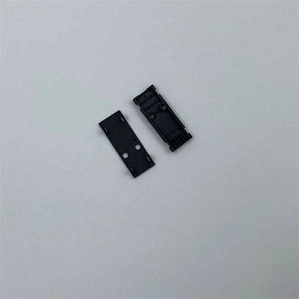
To properly remove the optical cable: Locate the port > Stabilize the device > Gently grasp & pull the plug (not the cable) straight out > Do the same with the other end > Cover both connectors with plastic tips. To remove the plastic tip: Gently twist and pull off the protective plastic tip from. The first step in removing an optical cable is to identify which cable you need to remove. This may seem obvious, but it's important to ensure that you are removing the correct cable to avoid any damage or confusion. An optical cable is a type of fiber optic cable that transmits light signals. If your TV is connected to your digital device via an optical cable that needs to be unplugged, and yet you don't know how to remove it, then you are just in the right place. You can easily remove it simply by holding the lock while pulling it towards you. more How to connect soundbar to TV with HDMI and Optical Cable instead of HDMI ARC! Inserting optical cable to your TV or soundbar could be a bit tricky. The process varies depending on the type of connector, but the principle remains the same: unlock, then remove. While specific designs may differ, the general procedure involves a. This guide outlines proper methods to safely remove fiber optic cable from modems in your home or office. As an experienced technology writer who has covered broadband advancements for over a decade, I aim to provide readers with trustworthy instructions endorsed by industry experts.
[PDF]
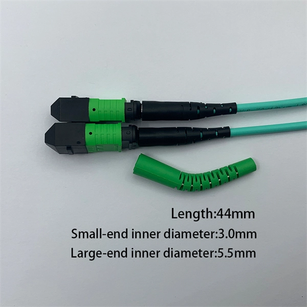
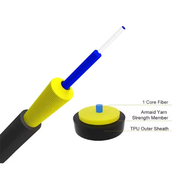
Figure 1 is a diagram of the basic construction of both loose-tube and tight-buffer fiber optic cable. An optical fiber cable is a complex structure designed to protect fragile glass fibers that transmit digital data using light signals. This advanced cabling solution allows fast, secure data transfer and telecom over long distances. Understanding the components within a fiber optic cable enables. A fiber optic cable consists of five basic components: the core, the cladding, the coating, the strengthening fibers, and the cable jacket. When searching for a fiber optic cable, we need to pay attention not only to the connectors, such as SC to ST fiber cable, LC to SC fiber patch cable, or SC to. Optical fibers are circular dielectric wave-guides used to contain and transmit light over short or long distances. They consist of three elements as shown in Figure 1: a central core, cladding and a protective coating. Understanding its internal structure is essential to appreciate how it functions efficiently in various applications, from telecommunications to medical devices. The core is the. 3,260 optical fiber structure illustrations, drawings, stickers and clip-art are available royalty-free for download. Multimode all-media self-supporting fiber optic cable structure isolated on white. More specifically, we can say that it is a waveguide that has the ability.
[PDF]

Distribution box The system diagram usually shows the electrical connection and configuration inside the distribution box in a graphical way, including busbars, circuit breakers, fuses, load devices and other elements. In practical applications, the corresponding system diagram can be drawn. A wiring diagram symbols chart is a visual representation of the various symbols used in electrical diagrams. It provides a quick and easy reference guide to understanding the meaning behind each symbol. These symbols can represent different electrical components, such as switches, resistors. Hey, in this article we are going to see the Single Phase Distribution Box Wiring Diagram and Connection Procedure. A distribution board or distribution box is where the main power supply is distributed to multiple loads. Understand its role in electrical systems and safety. It helps control and distribute electricity to different areas. Inside. In the world of electrical installations, the term DB box —short for Distribution Board box —refers to the central unit that distributes incoming electrical power to multiple outgoing circuits in a building. Whether you're powering up a residential home, a commercial office, or an industrial plant. Power distribution panel is used for utilization of equipment. A molded case circuit breaker are used which incomer supply is connected with LT panel and outgoing supply is connected width panel busbar.
[PDF]

In this guide, you will learn how to interpret network diagrams like a pro, from symbols and scope to segmentation, dependencies, troubleshooting, and security clues. A rack elevation diagram is a visual representation of the equipment and components contained within a rack in a data center or server room. It provides a clear overview of the physical layout of the rack, including the placement and positioning of servers, switches, storage devices, and other. Learn how to read and interpret network diagrams effectively to troubleshoot, validate security, and plan network changes with confidence. Have you ever opened a network diagram and felt like you were staring at a subway map with no station names? That is a common problem, even for experienced IT. Network cabinet cabling describes the structured connection and arrangement of all IT components in a server rack. The aim is a secure, maintainable and scalable operation of the network environment. The amount. A standard operating procedure, or SOP, is a set of step-by-step instructions compiled by an organization to help workers carry out complex routine operations. Work instructions should be very detailed on "how" to accomplish a specific job, task or assignment. It helps teams understand network architecture, data flow, and dependencies, making it easier to design infrastructure, troubleshoot issues, and plan.
[PDF]
This guide breaks down everything you need to know about electrical distribution boxes in plain English. We'll explain what they are, the different panel types you'll encounter, NEC 408 requirements that govern their installation, and common applications for each type. The power distribution boxes deliver electricity from the main electrical main to other circuits. Several distribution boxes are designed for specific use in offices or industries. Main Distribution Board (MDB) 2. Each. Distribution boxes, also known as electrical distribution boards or panels, are pivotal components in electrical systems, ensuring the safe and organized distribution of electrical power throughout residential, commercial, and industrial environments. It receives power from the main electrical supply and divides it into separate circuits, each. Electrical control panels and distribution boxes are the backbone of modern electrical systems. From powering homes and industrial facilities to supporting medium-voltage infrastructure, these enclosures ensure safe, efficient, and reliable power distribution. Whether it's a small electrical.
[PDF]
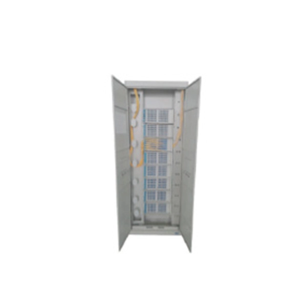
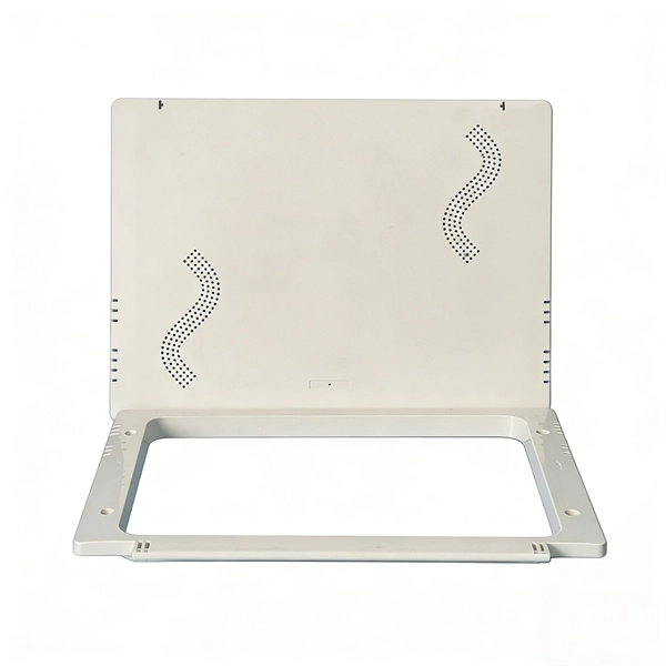
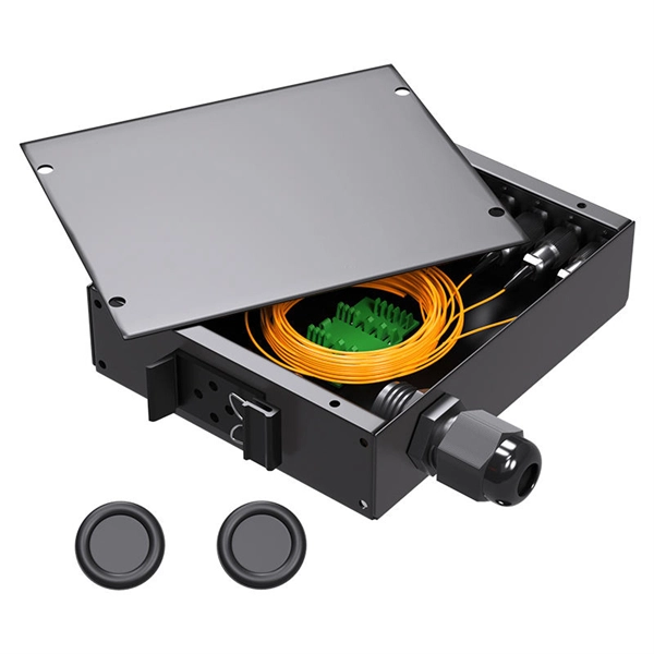
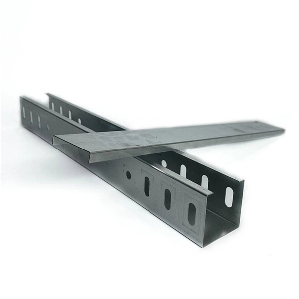
The 8 Port Fiber Access Terminal (FAT) is designed to connect feeder cables to subscriber drop cables for FTTH last-mile fiber connectivity; it can achieve direct or branch and terminal connection in FTTH or FTTB projects. FTB-SC8-WOPA type fiber optic terminal box is designed for FTTx application, which is cable to meet at least 8 users requirements. It can help splicing, splitting, storage and management with suitable space. Simple with light weight in design, special snap clip close system coinvent for user. ORCA® terminal optic box it is the best solution for indoor optical cable distribution or termination. The plastic case it is very light for a simple use. The FOTB fit the SC Simplex adapter (on request with ST and FC adapter). It is possible to buy the unloaded version (w/o Adapter) or the. Maximum capacity: 8 SC simplex, 8 LC duplex. The 8 port Fiber Distribution Box is sturdy in structure, lightweight in size, and easy to install. Built with high-density configurations and rugged materials, this MST box is perfect for installations in harsh environments like 4G/5G. The wall-mounted optic fibre termination box allows for easy organization of optic fibre cables (up to 4 fibres, depending on the installed adapters.
[PDF]
In 2011, the Malian government announced a 942 km fibre optic cable project linking Bamako-Gao-Kidal-Tin-Zaoutière to the Algerian border and Gap-Ansongo-Labezanga to the border of Niger. The project was funded by a $45 million loan from the Exim Bank of China.OverviewThis is a list of projects in. While are used to connect. This list was initially developed as part of AfTerFibre, a project to map terrestrial fibre optic cable projects in Africa. The project was sponsored by and, on completion, will be hosted by the UbuntuNet. • • • •.
[PDF]

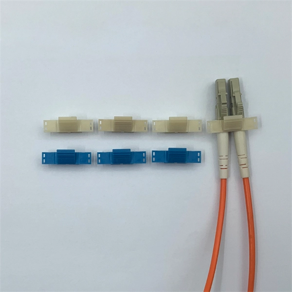
Fiber optic connectors can be categorized according to different standards such as utilization, fiber count, fiber mode, and transmission method. They are also divided into single-mode and multimode types based on their distinct characteristics. This guide will walk you through the most common fiber connector types, explaining their characteristics, advantages, and typical use cases. Whether you're planning an FTTH deployment, upgrading a data center, or working in telecom infrastructure, this guide will help you make informed decisions. Compared to Copper cables, Fiber connector types are incredibly varied. Where copper twisted pairs tend to terminate with an RJ45 plug, fiber optic connectors come in all sorts of shapes and sizes, with all manner of different use cases in mind. An optical fiber connector is used to join optical. With a wide variety of connector types available, choosing the right connector for your network can be challenging. Learn how each connector works, where it's used, and how to choose the right option for today's high-density, high-speed networks. It is a precise coupling device that joins fiber optic cables quickly, enabling faster connection and disconnection than splicing. The connector mechanically orients the fiber cores, allowing light to pass and travel through. In this guide, you'll explore various types of fiber optic cable connectors, each with unique features and best uses. We'll also provide practical advice.
[PDF]

The primary function of a fiber adapter panel is to provide a housing for fiber optic adapters or connectors. These adapters act as the interface between the terminated fiber ends and the active equipment, such as switches, routers, or servers. A fiber patch panel is a mounted enclosure—either rack-mounted or wall-mounted—used to terminate, manage, and interconnect multiple fiber optic cables. It acts as a hub for organizing splices and patch cords, streamlining fiber management and preserving signal integrity. This guide will focus on elucidating the aspects of the fiber patch panel, its accessories, the work done with such a device, and how to. Fiber optic networks are the backbone of fast, reliable internet and modern communications, but even the best fiber cables need the right connectors and patch panels to work efficiently. Connectors are the points where fiber cables link to devices, equipment, or other cables, and using the right. The fiber optic patch panel, also known as the fiber distribution panel, serves as the crucial component of the management of fiber optic cables. Also, the advantage of fiber optic patch panels is to reduce the loss of fiber optic transmission and facilitate engineers to troubleshoot. Serving as the network's centralized junction, it provides secure ports for both incoming and outgoing fibers, streamlining connection.
[PDF]
This guide will walk you through the most common fiber connector types, explaining their characteristics, advantages, and typical use cases. Created by the Fiber Optic Association as an educational project to help document the history of the development of fiber optics for communications. Since I was involved in fiber optics starting in the late 1970s, much of this is from personal experiences and memories. Whether you're planning an FTTH deployment, upgrading a data center, or working in telecom infrastructure, this guide will help you make informed decisions. This is the FOA's Online Guide To Fiber Optics, Fiber Broadband & Premises Cabling. It includes almost a thousand pages of materials created by the FOA covering the basics to advanced topics on fiber optics and premises cabling. The goal of this website is educating students, users, designers. Fiber connectors, also called fiber optic cable connectors, are often used to link optical fibers where a connect or disconnect capability is needed. Fiber optic cable connectors come in many configurations and usages, and simplify fiber optic cable installation and maintenance greatly. A number of. This tutorial will provide a brief analysis of the current fiber optic connectors market and a detailed introduction to Fiber optic connectors. Fiber optic cables are increasingly replacing.
[PDF]
There are several diagnostic methods to help troubleshoot fiber optic connectors, and the diagnostic method is to cross-section the fiber optic connector. This technology allows us to actually look inside the fiber optic connector to see defects and pinpoint the cause of. Fiber design and transmission technology have collaboratively evolved to increase bandwidth. Dig-ups dominate! Cablers have very little influence on the majority of causes of cable field failures. While a small percentage, we can examine the “intrinsic” cable failures and what is done to prevent. Connector failure is most frequently the result of a dirty or damaged end-face. Fiber-optic connector: SC type In the connector, the element that holds the fiber and provides the alignment positioning is the ferrule. The. In August of 1999, Boeing Corporation (Boeing) engineers being used on International Space Station flight a defect in the glass fiber (see Figure 1, “Rocket and NASA engineers and managers, Boeing created and reliability of the cable installed in the U. Fiber coupling can be accomplished by fusion splicing.
[PDF]