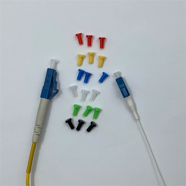
Once you have your modules and fiber in hand, the process is simple: Insert the SFP modules into the SFP or SFP+ port of your UniFi device. Plug in the fiber cable, LC connectors click right into the module. Power on both devices. Watch for a link light, if you see green . LC connectors are quickly becoming the connector of choice due to their compact size and outstanding performance. This guide will walk you through the key steps for properly connecting LC fiber connectors. LC fiber connectors feature a small form factor design that takes up very little space. LC (Lucent Connector) fiber connectors are small form-factor connectors widely used in telecommunications and data center environments. These connectors feature a push-pull coupling mechanism and a 1. 25mm ferrule, making them ideal for high-density applications. Understanding how to properly. By following these steps and precautions, you can ensure a reliable and high-quality connection with LC fiber connectors, enhancing the stability and performance of your network. The abbreviation LC for fiber optic connectors stands for Lucent Connector and literally means “translucent/transparent. The LC connector is about half the size of an SC connector. It meets TIA/EIA-604-10 standards, ensuring compatibility and performance across manufacturers. Learn how to use LC connectors for efficient networks.
[PDF]
* Bronze alloy bolts shall have a minimum tensile strength of 70,000 pounds per square inch. ** Bolts, cap screws, nuts, flat washers, locknuts: 18-8 alloy. Qualified to meet or exceed all the nationally recognized standards, including ANSI C119. 4 and NEMA CC1, the DMC Power system raises the quality, safety and productivity standard. Other aluminum compression connectors are made from com-mercially pure high conductivity wrought aluminum. Select type of connector from those listed below and follow the indicated procedure. ** Belleville Washers: 302 alloy. EX: TPC600-4N4-AA-GS TYPE TPC-N-AA Terminal Connector A C FIG. 3 T Terminal is designed to connect to aluminum or copper pads. Pad conforms to NEMA standards. 56 © 2011, AFL, all rights reserved. PP-3-00479. This publication contains the following new or updated information. This list includes substantive updates only and is not intended to reflect all changes. Added information about using a Top Hat Rail, catalog number 141A-AHR45, with a Adapter Extension Module, catalog number 141C-X40. Examples. We have recently reviewed our company's bus torque chart and found some of the values are in line with the bolt mfg suggestions (i. - 1/2" - 3/4" bolts). I started to update our torque chart to match the.
[PDF]

Step-by-step instructions on how to install fiber optic connectors like LC, SC, and ST. Includes tool recommendations, epoxy and polish method, and safety tips for installers and technicians. Even with sharing in efficiency, fiber connector installation is still an effort in which precision and safety form the central themes. A correct installation creates a low-loss, reliable connection essential for high-speed data transmission. While fiber optics enable speeds and distances copper can't match, the system's performance hinges. Next, we will introduce in detail the installation of several different types of fiber optic connectors. How To Connect Fiber Optic Cable To Connector? The connection methods for SC, FC, ST, and FT connectors with optical fibers are basically the same. Unlike foil strain gauges, fiber is often suitable for embedment. Sensuron's FOS offers hundreds to thousands of sensing points with a resolution of 1. 4 mm along a single sensing fiber. This video demonstrates the process of installing a fiber optic sensor to a substrate for measuring distributed mechanical strain. Fiber optic connectors are devices that join two fiber optic cables together, allowing the transmission of light signals with minimal loss. They come in various types, such as SC, LC, ST.
[PDF]

Learn how to properly install a pigtail connector in just a few easy steps. No description has been added to this video. Enjoy the videos and music you love, upload original content, and share it all with friends, family, and the world on YouTube. Pigtail connections are most frequently used to ground a switch or electrical outlet and for electrical devices that need to connect to multiple circuit wires. They also come in handy to lengthen circuit wires that are too short to reach a device. A pigtail is composed of three strands of wire. A pigtail connector is a short length of insulated electrical wire that is pre-attached to a device, terminal, or fixture, serving as a flexible bridge between the fixed wiring system and the component. Whether you are a DIY enthusiast or someone facing an electrical issue, understanding how to replace a pigtail connector can be invaluable. This article will walk you through the necessary steps and provide. This is where quality automotive connector replacement steps in. Often, rather than pay thousands of dollars for an entire harness, you can simply replace the damaged connector by a careful de-pin/re-pin or an accurate wire repair. Want more automotive electrical wire repair videos? Click Here Hear. The National Electrical Code (NEC) requires a pigtail to be at least six inches long. Although this standard applies to house wiring, we can use the same for vehicle wiring.
[PDF]
This guide will walk you through the most common fiber connector types, explaining their characteristics, advantages, and typical use cases. Created by the Fiber Optic Association as an educational project to help document the history of the development of fiber optics for communications. Since I was involved in fiber optics starting in the late 1970s, much of this is from personal experiences and memories. Whether you're planning an FTTH deployment, upgrading a data center, or working in telecom infrastructure, this guide will help you make informed decisions. This is the FOA's Online Guide To Fiber Optics, Fiber Broadband & Premises Cabling. It includes almost a thousand pages of materials created by the FOA covering the basics to advanced topics on fiber optics and premises cabling. The goal of this website is educating students, users, designers. Fiber connectors, also called fiber optic cable connectors, are often used to link optical fibers where a connect or disconnect capability is needed. Fiber optic cable connectors come in many configurations and usages, and simplify fiber optic cable installation and maintenance greatly. A number of. This tutorial will provide a brief analysis of the current fiber optic connectors market and a detailed introduction to Fiber optic connectors. Fiber optic cables are increasingly replacing.
[PDF]

In this step-by-step guide, we will walk you through the process, ensuring that you can seamlessly connect your optical cable and enjoy a clear and uninterrupted audiovisual experience. Optical cables are becoming increasingly popular for transmitting high-quality. Optical audio cables can easily improve your TV's sound by connecting to external speakers. Learning how to connect an optical cable is easy, but there are a couple of gotchas that you should know. Here are the basics: Identify the optical output; if there's a protective plastic cap, remove it. The most common types are: The Toslink optical cable is a standard for transmitting digital audio signals. It uses a plastic or glass fiber to carry light signals from one. You can connect an older flat screen TV to ANY Stereo system, Surround Sound system, or Soundbar. This video shows you step by step how to make audio connections using an digital optical cable. You can use an optical connection even if your audio system does not have an optical socket, and by using. One of the easiest ways to achieve high-quality sound is to connect your TV to a home theater system or soundbar. Easily connect your optical audio cable to your TV! Follow our step-by-step guide for a hassle-free setup and enjoy crystal-clear sound. No wonder how to improve TV sound, right? When the sound is weak, for example, when using an analog sound source, then an optical audio cable possibly will be the.
[PDF]

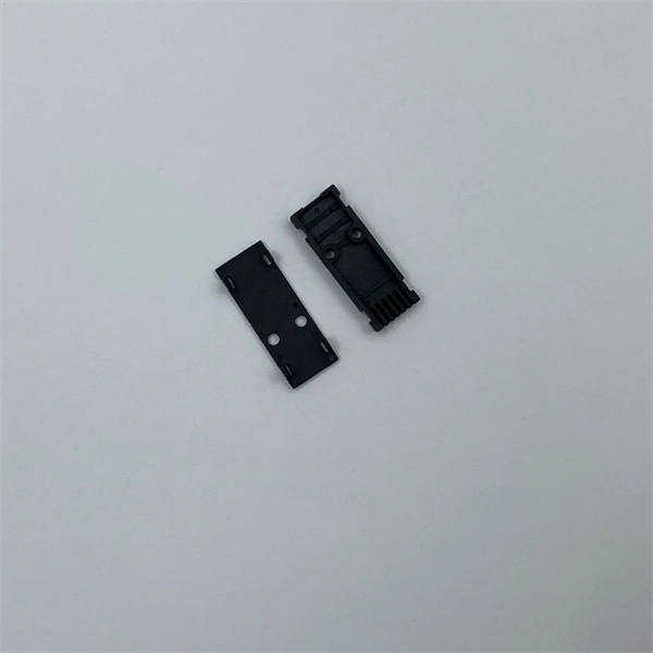
The primary function of a fiber adapter panel is to provide a housing for fiber optic adapters or connectors. These adapters act as the interface between the terminated fiber ends and the active equipment, such as switches, routers, or servers. A fiber patch panel is a mounted enclosure—either rack-mounted or wall-mounted—used to terminate, manage, and interconnect multiple fiber optic cables. It acts as a hub for organizing splices and patch cords, streamlining fiber management and preserving signal integrity. This guide will focus on elucidating the aspects of the fiber patch panel, its accessories, the work done with such a device, and how to. Fiber optic networks are the backbone of fast, reliable internet and modern communications, but even the best fiber cables need the right connectors and patch panels to work efficiently. Connectors are the points where fiber cables link to devices, equipment, or other cables, and using the right. The fiber optic patch panel, also known as the fiber distribution panel, serves as the crucial component of the management of fiber optic cables. Also, the advantage of fiber optic patch panels is to reduce the loss of fiber optic transmission and facilitate engineers to troubleshoot. Serving as the network's centralized junction, it provides secure ports for both incoming and outgoing fibers, streamlining connection.
[PDF]
In 2011, the Malian government announced a 942 km fibre optic cable project linking Bamako-Gao-Kidal-Tin-Zaoutière to the Algerian border and Gap-Ansongo-Labezanga to the border of Niger. The project was funded by a $45 million loan from the Exim Bank of China.OverviewThis is a list of projects in. While are used to connect. This list was initially developed as part of AfTerFibre, a project to map terrestrial fibre optic cable projects in Africa. The project was sponsored by and, on completion, will be hosted by the UbuntuNet. • • • •.
[PDF]
Fiber optic connectors are the backbone of high-speed data transmission, but choosing the right interface—SC, LC, or MPO—can make or break your network's efficiency. In this head-to-head comparison, we analyze their size, port density, performance metrics, and ideal use cases, backed by data charts. They use precision ferrules and alignment sleeves to connect two fiber cores, maintaining light transmission efficiency. Because of this, it's no surprise that fiber optic connectors are in high demand across several industries. Their primary function is to precisely align the end faces of two optical fibers via an intricate mechanical structure to minimize optical signal transmission loss. The basic structure includes components such as. Fiber optic connectors are essential components in optical communication systems, enabling quick and stable connections between fibers. They are. LC, SC, FC, ST, MPO/MTP compared: ferrule sizes, polishing types, insertion loss, and a decision flowchart to choose the right fiber connector for your application. This allows for quickly connecting and disconnecting of fiber optic cables without splicing. The connector features a ferrule, the connector end piece that holds and secures the fiber and aligns it for light.
[PDF]

This report covers the optical, environmental, and mechanical performance of the LC-UPC, singlemode fiber optic BOAs, provided by Tyco Electronics, Fiber Optics Business Unit. Qualification testing was completed by a third party in July 2004. IDEAL FOR DEBUGGING OPTICAL POWER PERFORMANCE & OPTICAL INSTRUMENT CALIBRATION CORRECION & FIBER SIGNAL ATTENUATION. As optical passive devices, FS attenuators are mainly used in fiber optic to debug optical power performance & optical instrument calibration correction & fiber signal. L-com offers an extensive line of dual wavelength (1310/1550nm) Singlemode fiber optic attenuators. These versatile in-line attenuators are the perfect solution for attenuating Singlemode fiber connectors for both lab and commercial applications. Constructed of the highest quality materials and. zation system's perfo. the power of an optical signal. Our LC/APC single mode attenuators can handle a maximum o 1 watt of optical input power. This device contains one ale and one female LC/APC port. LC/APC optical attenuators can be ordered in attenuation. Fixed loopback type attenuators from OMC offer defined control of optical signals in both integrated and add-on products. Depending on the project or need, fixed attenuators can limit (attenuate) the amount of light passing through to the exact levels your project or application requirement.
[PDF]

This guide provides a fully updated and industry-ready overview of LC fiber optics, explaining the origin and design of LC connectors, their key features, and the complete ecosystem of LC-based products used in modern networking. It covers LC connectors, LC patch cables, uniboot designs, armored. LC stands for Lucent Connector (also colloquially “Little Connector”). It was introduced by Lucent Technologies to deliver small form factor (SFF) optical connections that match the density of RJ-45 copper ports. 25 mm ferrule (half the size of SC's 2. 5 mm) enables twice the port. Fiber optic connectors are used to the mechanical and optical means for cross connecting fibers. Fiber optic connectors can also be used to join fiber cables to transmitters or receivers. As a small-form-factor (SFF) interface, LC has become the default duplex connector in enterprise LANs, telco closets, and data-center topologies because it balances density, repeatability, and cost. SC connectors were originally designed for FTTH, but they were gradually popularized and used on a large scale due to their small size and convenience. You may find LC connector has a strong family which includes but not limited to LC optical fiber connectors, LC fiber patch cables, LC fiber.
[PDF]
LC connectors play an integral yet often overlooked role in enabling high-speed fiber optic communications. This guide dives into the engineering behind these compact connectors, their functionality, performance metrics, and applications across modern networks. LC connectors are a ubiquitous fiber. LC connectors provide reliable and high performance connectivity in fiber optic networks. The guide covers in depth their features, types, installation techniques, troubleshooting and applications. Learn how to use LC connectors for efficient networks. As a small-form-factor (SFF) interface, LC has become the default duplex connector in enterprise LANs, telco closets, and data-center topologies because it balances density, repeatability, and cost. This guide walks. It covers LC connectors, LC patch cables, uniboot designs, armored and ultra-low-loss variants, LC adapters and patch panels, LC attenuators, MTP/MPO-to-LC cassettes, LC-interfaced transceivers, and LC media converters. It also includes practical selection guidance, real-world deployment scenarios. Fiber optic connector is a device used to connect optical fibers, capable of transmitting and receiving optical signals. There have been many types of connectors developed for fiber cable. Single mode networks have used FC or SC.
[PDF]
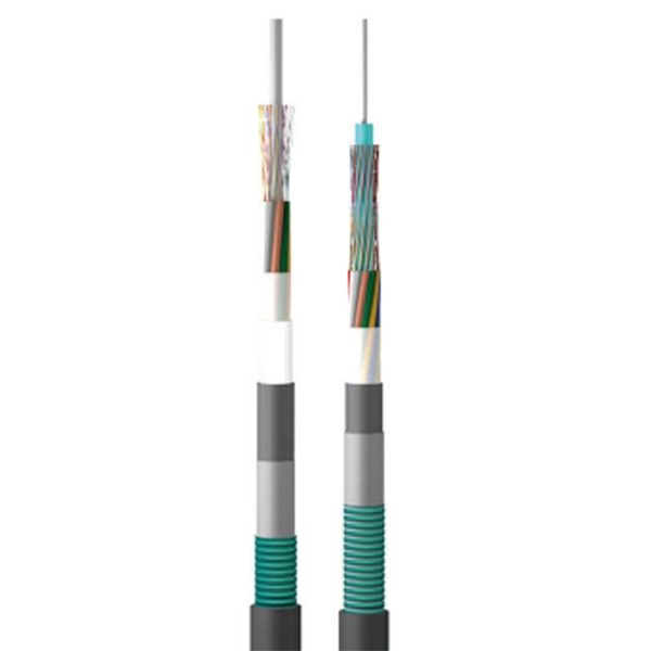
Here's a quick guide to make sure your fiber optics sail through the cold season: While fiber optics are tough, cold temps can cause trouble. Water in cables can freeze, potentially harming connections. Ensure tight seals on cable joints and connectors to. The fiber carries data as pulses of light, and has nowadays overtaken copper wire as the medium of choice – primarily because it is lower cost, faster and less bulky. Optical fiber is also harder to hack than copper, making it more secure and safer because it doesn't generate heat. There is. Fiber optic cables are the backbone of modern high-speed data transmission, offering unparalleled speed and reliability compared to traditional copper wires. Summary : Winter weather generally has minimal impact on fiber optic cables since they transmit data through light rather than electricity, making them resistant to temperature-related signal loss. Waterproofing prevents icy.
[PDF]

A ladder type cable tray tee is a fitting used to create a branch in a cable tray system, allowing cables to be routed in three directions. Its "T" shape provides a secure and efficient way to split cables from a main tray into two separate paths, ensuring organized and flexible. A cable tray tee and tee cover are components used in cable management systems to support and protect electrical and data cables. Here's a brief explanation of each:. Rigid steel cable tray tee fitting with zero tangent, safety bottom, and full accessory support. ventilation to heat producing cable such as power communication and other with the same or different width of the cable run. All fittings are available in sizes and types corresponding to the straight cable tray sections. These fitting are including: elbow, horizontal cross, vertical inside. NOTE : Equal or un equal tees can be supplied. When ordering state widths W1xW2xW3.. Office: 147/22 Nguyen Sy Sach Street, 15 Ward, Tân Binh Dist, HCMC,VN. Is it possible to connect 2 cabletrays with a "branch piece (left picture)" instead of a "tee (right picture)". The tee has 3 connectors, the branch piece only has 1 connector. I would like to ajust the "Type properties -> Fittings -> Tee" with the branch family, but can't get it accomplished.
[PDF]

Cable Trays* — Max two 24 in. (610 mm) wide by max 6 in. (151 mm) deep open-ladder cable tray with channel-shaped side rails formed of 0. 54 mm) thick aluminum or min 0. In practice, cable tray dimensions are a system of interrelated measurements —width, depth, length, and material thickness—that directly affect cable fill compliance, heat dissipation, structural loading, and long-term expandability. From an engineering standpoint, cable tray dimensions are not. Perforated Cable Tray System expertly constructed from high-grade stainless steel, offering exceptional durability and resistance to corrosion. With side height 100mm. A properly designed and installed cable tray system will provide. Studs — Wall framing to consist of wood studs or channel shaped steel studs. Wood studs to consist of nom 2 by 4 in. Additional studs shall be used to completely frame. Best Size: Here, deep trays (75mm to 150mm) are used since power cables are typically thick and heavy. Data cables, such as your Wi-Fi or computer ones, are extremely sensitive. They do not get hot; however, they do not like to hang or sag. In case a data cable folds in an excessive manner, the. ect the minimum bend ra-dius for cables as they exit the bottom of the cable tray. A rung spacing of 6 to 9 inches (150 to 230 mm) is preferable when the cable tray cont d for instrumentation and control applications that require additional protec eferred to support and protect numerous small.
[PDF]