
5 dB depending on splitter type. Common planning value: 0. Optional: patch panels, attenuators, or extra components. Helps cover dirt, aging, and measurement tolerances. Adds Rx power and margin calculation. Calculate insertion loss for passive optical splitters in PON and distribution networks. Power is divided equally among output ports. Excess loss accounts for manufacturing imperfections, typically 0. DISCLAIMER: These calculators are provided for. Optical splitters, encompassing FBT (Fused Biconical Taper) couplers and PLC (Planar Lightwave Circuit) splitters, are prevalent passive optical devices designed to divide fiber optic light into multiple segments based on a specified ratio. Fiber optic splitters are vital components within. In fiber optic networks, particularly in FTTx (Fiber to the x) and PON (Passive Optical Networks) deployments, splitters play a central role in distributing the optical signal from a single source to multiple destinations. Optional: patch. Understanding optical splitter loss isn't just about plugging numbers into a calculator. It's about knowing what factors contribute to that loss, how manufacturers specify it, and how it impacts the overall performance and reach of your network. Understanding the types of splitters, their impact on network performance, and how to measure their losses ensures high-quality network operation and facilitates optimal splitter selection based on.
[PDF]

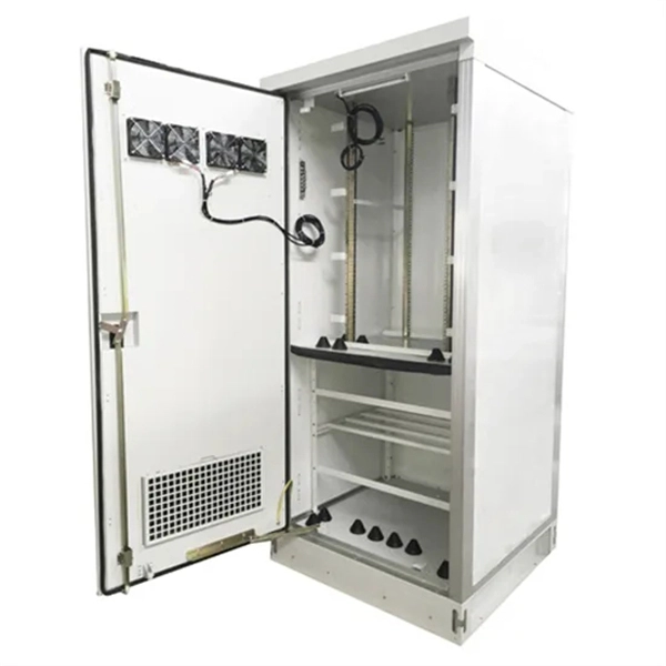
In this guide, you will learn how to interpret network diagrams like a pro, from symbols and scope to segmentation, dependencies, troubleshooting, and security clues. A rack elevation diagram is a visual representation of the equipment and components contained within a rack in a data center or server room. It provides a clear overview of the physical layout of the rack, including the placement and positioning of servers, switches, storage devices, and other. Learn how to read and interpret network diagrams effectively to troubleshoot, validate security, and plan network changes with confidence. Have you ever opened a network diagram and felt like you were staring at a subway map with no station names? That is a common problem, even for experienced IT. Network cabinet cabling describes the structured connection and arrangement of all IT components in a server rack. The aim is a secure, maintainable and scalable operation of the network environment. The amount. A standard operating procedure, or SOP, is a set of step-by-step instructions compiled by an organization to help workers carry out complex routine operations. Work instructions should be very detailed on "how" to accomplish a specific job, task or assignment. It helps teams understand network architecture, data flow, and dependencies, making it easier to design infrastructure, troubleshoot issues, and plan.
[PDF]

Distribution box The system diagram usually shows the electrical connection and configuration inside the distribution box in a graphical way, including busbars, circuit breakers, fuses, load devices and other elements. In practical applications, the corresponding system diagram can be drawn. A wiring diagram symbols chart is a visual representation of the various symbols used in electrical diagrams. It provides a quick and easy reference guide to understanding the meaning behind each symbol. These symbols can represent different electrical components, such as switches, resistors. Hey, in this article we are going to see the Single Phase Distribution Box Wiring Diagram and Connection Procedure. A distribution board or distribution box is where the main power supply is distributed to multiple loads. Understand its role in electrical systems and safety. It helps control and distribute electricity to different areas. Inside. In the world of electrical installations, the term DB box —short for Distribution Board box —refers to the central unit that distributes incoming electrical power to multiple outgoing circuits in a building. Whether you're powering up a residential home, a commercial office, or an industrial plant. Power distribution panel is used for utilization of equipment. A molded case circuit breaker are used which incomer supply is connected with LT panel and outgoing supply is connected width panel busbar.
[PDF]
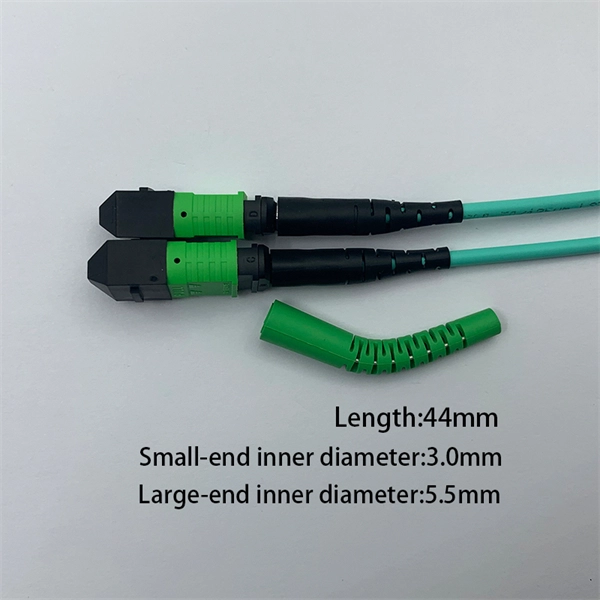
Figure 1 is a diagram of the basic construction of both loose-tube and tight-buffer fiber optic cable. An optical fiber cable is a complex structure designed to protect fragile glass fibers that transmit digital data using light signals. This advanced cabling solution allows fast, secure data transfer and telecom over long distances. Understanding the components within a fiber optic cable enables. A fiber optic cable consists of five basic components: the core, the cladding, the coating, the strengthening fibers, and the cable jacket. When searching for a fiber optic cable, we need to pay attention not only to the connectors, such as SC to ST fiber cable, LC to SC fiber patch cable, or SC to. Optical fibers are circular dielectric wave-guides used to contain and transmit light over short or long distances. They consist of three elements as shown in Figure 1: a central core, cladding and a protective coating. Understanding its internal structure is essential to appreciate how it functions efficiently in various applications, from telecommunications to medical devices. The core is the. 3,260 optical fiber structure illustrations, drawings, stickers and clip-art are available royalty-free for download. Multimode all-media self-supporting fiber optic cable structure isolated on white. More specifically, we can say that it is a waveguide that has the ability.
[PDF]

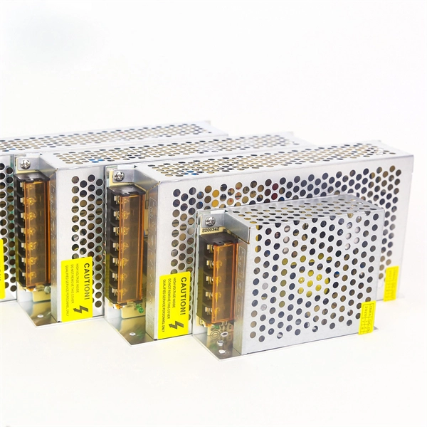
This AutoCAD DWG file includes a complete Single Line Diagram (SLD) of a Distribution Board, showing circuit breakers, wiring connections, and load distribution for lighting, power, and mechanical systems. Knowledge of the basic electrical power distribution system and its components will help the operator understand the importance of electrical power distribution systems. Failure-free power e. Overlapping protective zones a. Protective relays A single, or one-line. A power distribution box (also called PDU or distro) directs electricity from a main source to multiple circuits. It acts like a hub or traffic controller, managing power flow to different areas or devices. Key components include circuit breakers, fuses, bus bars, and internal wiring for safety and. Check electrical parameters: First understand the basic electrical parameters of Distribution box so that you can have a general understanding of the capacity and performance of the distribution box. Analyze the incoming line part: Determine the incoming line source of the distribution box and. ndards and conformity assessment activities in the United States. ANSI facilitates and promotes voluntary consensus standar rty or economic loss due to fire, electrical and related hazards. Now, let's look at how consumers use electrical power. What is a Electrical Power Distribution System? 1. Power supply is received from LT panel and distributed to the outgoing feeders for utilization.
[PDF]

The following wiring diagram shows the installation of a 60A subpanel for both 120V and 240V. You may use the current rating according to the system requirement i. 50A, 60A, 100A, 150A and so on. We have used 60A for illustration purposes only. Click image to enlarge. Primary distribution systems consist of feeders that deliver power from distribution substations to distribution transformers. A feeder usually begins with a feeder breaker at the distribution substation. Many feeders leave substation in a concrete ducts and are routed to a nearby pole. At this. An electrical sub panel, also known as a sub distribution board or sub circuit breaker panel, is a smaller secondary panel connected to the main electrical panel in a building. It serves as an extension of the main electrical panel to distribute power to different areas or circuits within a. secondary unit substation is a close-coupled assembly consisting of enclosed primary high voltage equipment, three-phase power transformers, and enclosed secondary low-voltage equipment. We have used 60A for illustration. Installing a subpanel is best handled by a professional electrician, but if you're curious how it's done, here is a brief overview of how to install a subpanel breaker box. Equipment Identify the location where you're adding a second breaker box. This information will help as you consider a Sub-Panel and its size. Electrical Tips and Be Sure to.
[PDF]

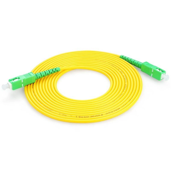
This guide covers the essential tools and step-by-step procedures for low-loss fiber optic cable repair. Understanding the causes and types of fiber optic cable damage helps detect issues early and determine when repair is needed. Construction Activities: Accidental damage during construction. Step1 : Identify the optical cabinet and network operating center, and find the fiber optic splitter. Step 2: Identify the splitter number. Step 4: Find the optical fiber port and cable sequence that leads to the user. 2) The. This complete guide covers everything from identifying causes of failure to advanced repair techniques, drawing on the latest industry standards and innovations. Whether you're a network technician, IT professional, or telecom operator, you'll find practical steps, tools, and tips to restore. If you accidentally break a fiber optic patch cord in your server room or in any of your switch gear, now you can repair it on the spot and get back up and running in minutes. Adhering to precise methodologies, we can mend impaired cables. By understanding these key elements and following the outlined steps, you can effectively repair fiber optic cables and maintain the high-performance network necessary for today's demanding communication needs. When it comes to ensuring nice network experiences for users, the condition of a fiber.
[PDF]

This diagram shows how the RJ45 cable is connected to the PoE switch, allowing it to power devices such as IP phones and cameras. In this article, we will explore the wiring diagram for a PoE switch, which provides a visual representation of how the switch connects to various devices. Each device is represented by a. Do you want to set up a new computer network in your home or office? Chances are, you'll need a Poe switch wiring diagram. Not only do these diagrams provide all the information you need to install a network, but they also help make the process easier and more efficient. For those who don't know. A PoE Switch, also known as Power over Ethernet Switch, is a network device that allows users to power and connect devices such as IP cameras, VoIP phones, and wireless access points. In essence, a PoE Switch can be described as regular switch with added ability of Power over Ethernet which allows. PoE technology enables the transmission of both data and power over a single ethernet cable, simplifying network setups and eliminating the need for additional power sources. This is particularly useful in scenarios where devices like IP cameras, wireless access points, or VoIP phones need to be. Here, you can see the details, Keep the copper strips towards your face and count the pin number or pin position from left to right. The T568B also has a total of eight pins and sight different colors.
[PDF]
See a sample diagram and download it in different formats. Electrical enclosure sizes are not universal, but most manufacturers follow common size families. This guide explains typical wall-mount and floor-standing dimensions, how to read catalog sizes, and how to choose the right enclosure size for your layout. What Are Electrical Box Dimensions? Electrical box dimensions typically refer to: Correct dimensions ensure:. Solid rubber (construction) distribution box suitable for construction and industry according to EN-61439-4. Available from stock. The only one in the Benelux with a Dekra quality mark. Distribution boxes 32 Amp. Explorez notre Guide Complet du RGIE : Schémas Électriques, Conseils de Conformité, Assistance Gratuite pour la Sécurité et la Mise aux Normes des Installations, et Accès Direct aux Électriciens et Agences Agréées. Discover easy access to the Belgian Electrical Regulations resources, structured. Sheet Electrical: Electricity symbols for floor plans (based on Belgium regulations). Learn more about these objects, how they can be added to your Dia toolbox and how you can draw your diagrams with them. Boxes distribute low currents in an area equipped with 1 to 12 RJ 45 sockets. They centralise connections to ensure flexibility and that the installation is up to date. Area boxes can be installed in technical flooring or in false ceilings.
[PDF]
Welcome to our channel! In this video, we'll walk you through the process of wiring a home distribution box with a detailed connection diagram. It serves as a central hub for distributing electricity throughout a building, ensuring that power is delivered safely and efficiently to all the required locations. And all the switching and protective devices are installed in the. Distribution Board or DB is an electricity supply system or a common enclosure that distributes the electrical power feed into subcircuits. It includes isolator, RCCB (Residual current circuit breaker) or RCD (Residual-current device) devices, protective fuses or MCB's (Miniature Circuit Breaker). That's why having a clear, detailed diagram of your home's distribution board wiring is essential. A distribution board (also known as a service panel or breaker box) is a centralized collection of circuit breakers, fuses, and/or relays used to control and protect the wiring in a home.
[PDF]

The 6 terminal junction box wiring diagram provides a visual representation of how the various wires and connections should be made within the box. It shows the layout and arrangement of the terminals, as well as the color coding and labeling of the wires. Hey, in this article we are going to see the Single Phase Distribution Box Wiring Diagram and Connection Procedure. A distribution board or distribution box is where the main power supply is distributed to multiple loads. It provides a quick and easy reference guide to understanding the meaning behind each symbol. These symbols can represent different electrical components, such as switches, resistors. This technical article aims to take you on a journey through the fundamental terminals and other connecting elements of wiring diagrams and electrical schematics and to delve into the minute intricacies of the components that form them. From the familiar male and female terminals that form the. An electrical panel box, also known as a breaker box or a distribution board, is a crucial component of any electrical system. Whether you're an electrician or a DIY enthusiast, this guide will help you understand the basics of home electrical distribution. more Welcome to our. The Engineering Base terminal block diagram is a special template showing information about terminal blocks, terminals and their accessories. There are two methods for creating a terminal block.
[PDF]
Japan breaks the world record internet speed record: 1. 02 petabits per second via fiber optics, 4 million times faster than broadband. Breakthrough uses 19-core optical fiber, matching current cable thickness but with 19x the capacity. Technology maintains speed over 1,120 miles, solving long-distance signal loss with. Most fiber providers offer plans with speeds of at least Gbps (1,000 Mbps), but this is by no means the limit to fiber technology. Some providers already offer multigigabit speeds, such as AT&T's 5 Gbps (5,000 Mbps) fiber plan. Google owns an undersea fiber-optic cable connecting North America and. There is a new world record for fiber speed: 1. Here is how these fiber speed records compare: Faster fiber optic networks help you get real-time updates for. At the heart of this breakthrough – driven by Japan's National Institute of Information and Communications Technology (NICT) and Sumitomo Electric Industries – is a 19-core optical fiber with a standard 0. 125 mm cladding diameter, designed to fit seamlessly into existing infrastructure and. In a groundbreaking feat that promises to redefine global communication capabilities, Japanese researchers have achieved an unprecedented data transmission speed of 1. The achievement yielded a capacity–distance product of 1. That rate is about four million times higher.
[PDF]

Cable Trays* — Max two 24 in. (610 mm) wide by max 6 in. (151 mm) deep open-ladder cable tray with channel-shaped side rails formed of 0. 54 mm) thick aluminum or min 0. In practice, cable tray dimensions are a system of interrelated measurements —width, depth, length, and material thickness—that directly affect cable fill compliance, heat dissipation, structural loading, and long-term expandability. From an engineering standpoint, cable tray dimensions are not. Perforated Cable Tray System expertly constructed from high-grade stainless steel, offering exceptional durability and resistance to corrosion. With side height 100mm. A properly designed and installed cable tray system will provide. Studs — Wall framing to consist of wood studs or channel shaped steel studs. Wood studs to consist of nom 2 by 4 in. Additional studs shall be used to completely frame. Best Size: Here, deep trays (75mm to 150mm) are used since power cables are typically thick and heavy. Data cables, such as your Wi-Fi or computer ones, are extremely sensitive. They do not get hot; however, they do not like to hang or sag. In case a data cable folds in an excessive manner, the. ect the minimum bend ra-dius for cables as they exit the bottom of the cable tray. A rung spacing of 6 to 9 inches (150 to 230 mm) is preferable when the cable tray cont d for instrumentation and control applications that require additional protec eferred to support and protect numerous small.
[PDF]
Open a browser and type https://speed. is/id/telkom-indonesia/. Select a Host ISP or let it choose the optimal ISP automatically. Press the 'GO' button to start the Internet Speed Test. Enter your zip code to tailor the results specifically to your area. Join us in providing the world's most accurate speedtest platform. How Much Speed Do You Need? © 2006-2026 Ookla, LLC., a Ziff Davis company. Ookla ®, Speedtest ®, and Speedtest Intelligence ® are among the. Telkom Indonesia Internet Speed Test checks how fast is your internet speed. is will test download, upload, ping, and jitter speed. Select a Host ISP or. When you use Speed Test, Cloudflare receives the IP address you use to connect to Cloudflare's Speed Test service. Cloudflare uses your IP address to estimate your geolocation (at the country and city levels) and to identify the Autonomous System Number (ASN) associated with your IP address. net's Download Speed Test and Upload Speed Test log connection information to allow users to research real world Internet speed test results. This tool can average connection speed for any Internet.
[PDF]
Cable is usually faster than DSL as it has more bandwidth. Fiber internet, on the other hand, offers faster speeds and higher capacity overall. This is made possible because light signals travel faster and carry more information than electrical signals. Cable internet connections sit somewhere in the middle in the internet hierarchy: faster than DSL and satellite, but behind fiber. These connections utilize coaxial cables, which are made of copper, instead of fiber optic cables, which use small, flexible strands of glass or plastic. Because it's a. Whether powering a 5G network across a city or delivering gigabit internet to a rural household, fiber optic cable speed defines the backbone of digital infrastructure. This comprehensive guide explores what drives fiber optic speeds, how they compare to traditional alternatives, and how Dekam. Cable transmits data through copper coaxial cables (with an inner conductor and a protective outer jacket). Fiber-optic internet, also known as "fiber", transfers light signals along thin strands of glass.
[PDF]
