A8: Yes, multimode fiber optic cable can support high-speed data transmission depending on the fiber type and network equipment used. Multimode fiber (MMF) is an optical fiber designed to carry multiple light propagation paths—or modes—simultaneously. This is made possible by its relatively large core diameter, typically 50 or 62. 5 microns, compared to the ~9-micron core in single-mode fiber. The wider core accepts light from. Multi-mode optical fiber is a type of optical fiber mostly used for communication over short distances, such as within a building or on a campus. Multi-mode links can be used for data rates up to 800 Gbit/s. Multi-mode fiber has a fairly large core diameter that enables multiple light modes to be. In the realm of telecommunications and networking, multimode fiber optic cable plays a crucial role in efficiently transmitting data over short to medium distances. This guide aims to provide a concise understanding of multimode fiber optic cable and its applications. These fiber cables are structurally designed to transmit several light signals simultaneously, each of which is directed. Unlike copper cables, which rely on electrical signals, fiber optics use pulses of light to transmit data—offering unmatched bandwidth, low interference, and long-distance capabilities. But not all fiber cables are created equal: multimode (MM) and single mode (SM) fibers are the two primary types.
[PDF]
Single mode and multimode fiber optic cables are two different types of fiber optic cable aimed at different use cases. Single mode cables are typically made with a single strand of glass at their core, leading to a n.
[PDF]

Join Jake from Omnitron in this comprehensive tutorial. Understand the nuances of single-mode and multimode fibers, and how to bridge the gap using media converters. Enhance your tech knowledge and. But what happens when you need to connect an existing multi-mode campus network to a new single-mode service provider link? You can't just splice them together. This is where fiber conversion comes in. This guide will break down the professional methods to achieve seamless single-mode to multi-mode. Single-mode (SMF) and multi-mode fiber (MMF) use different core sizes, sources and wavelengths. These differences determine which transceivers work with which fiber and how far signals can travel. Let's analyze the differences between multimode and single-mode fiber to understand why networks require fiber mode conversion and. How can we convert the multimode to a singlemode fiber system? This complete guide will provide answers to these questions. That is because SMF and MMF have. There are two main types of fiber optic cables: single mode and multimode. Although they can do the same job in some instances, the different construction methods make each of them better suited to certain tasks and budgets. What if end B is located in another building, dozens of kilometers far away from end A? Or end B equipment is single-mode or must use a single-mode fiber connection? In the former case, you.
[PDF]
While most Rayleigh based fiber sensors use single mode fiber, multimode fiber has the potential to provide lower noise due to the higher capture fraction of Rayleigh scattered light, higher non-linear thresholds, and the ability to avoid signal fading by measuring many. While most Rayleigh based fiber sensors use single mode fiber, multimode fiber has the potential to provide lower noise due to the higher capture fraction of Rayleigh scattered light, higher non-linear thresholds, and the ability to avoid signal fading by measuring many. Speckle imaging through single multimode fibers (MMFs) has garnered significant attention for its minimally invasive nature and high imaging resolution. However, the prevalent fully serial sampling approach severely limits imaging speed. A convolutional neural network is utilized to establish the mapping relationship between speckle and Stokes parameters. The lowest root-mean-square error of the estimated SOP on the.
[PDF]

The goal is to fuse the two fibers together in such a way that light passing through the fibers is not scattered or reflected back by the splice, and so that the splice and the region surrounding it are almost as strong as the intact fiber. Fusion splicing is the process of fusing or welding two fibers together usually by an electric arc. Fusion splicing is the most widely used method of splicing as it provides for the lowest loss and least reflectance, as well as providing the strongest and most reliable joint between two fibers. Fiber Stripping: Selecting Precise Tools and Techniques Selecting the appropriate stripper will depend on the fiber coating diameter. This will typically be 250µm for bare fibers and 900µm for coated fibers. Reputable companies like Jonard, Fujikura, and INNO provide multi-hole strippers calibrated. Fiber misalignment and fiber geometry mismatch (e., core size, core-to-clad concentricity, core and cladding non-circularity, numerical aperture, etc. ) can result in real power loss across a splice joint. However, differences in the backscattering coefficients between two fibers can also show up. Fiber splicing means joining two optical fibers (permanently or temporarily) such that light guided in one fiber and reaching the joint (splice) can be transferred into the second fiber with low insertion loss.
[PDF]

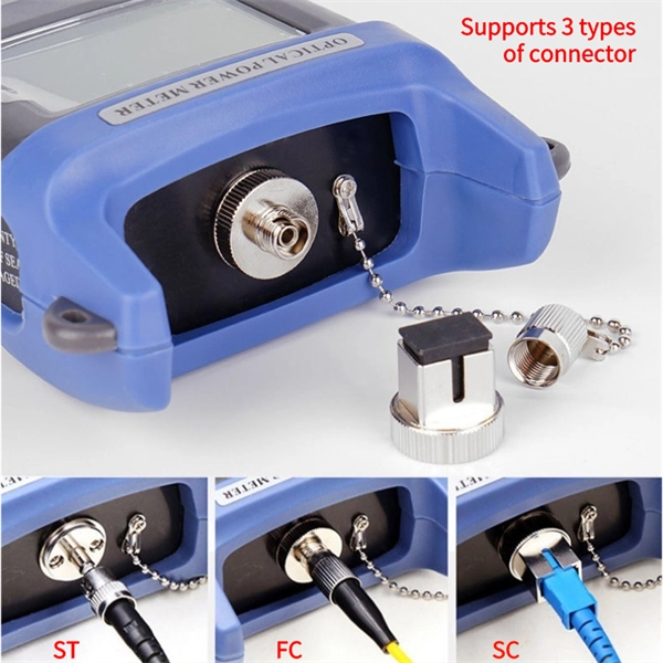
Since the earliest days of fiber optics, multimode cables have typically been color‑coded orange, black, or gray, while single‑mode cables are marked in yellow. For example, cable jacket color typically defines the fiber type, and can differ based on mode and performance level. These colors are typically chosen by industry standards bodies. However, there are some non-standardized colors and inconsistencies that you should be aware of. However, with the introduction of metallic connectors like FC and ST—whose bodies are difficult to color‑code—colored strain relief boots. Multimode fiber (MMF) is a kind of optical fiber mostly used in communication over short distances, for example, inside a building or for the campus. Multimode fiber optic cable has a larger core, typically 50 or 62. 5 microns that enables multiple light modes to be propagated. Because of this, more. Originally developed by the Electronic Industries Alliance (EIA) and the Telecommunications Industry Association (TIA), the TIA-598-D standard (formerly EIA/TIA-598) remains the most recognized color-coding system for optical fibers worldwide. On the right, the yellow patchcord indicates singlemode fiber and the blue connector means it is a regular PC polished connector, If it were an APC connector, it would be green. Perhaps nothing is.
[PDF]

The fusion method fuses the fiber cores together with less attenuation. Fusion splicing stands out as a superior technique for joining optical fibers, offering a seamless, low-loss connection that is crucial for reliable fiber optic networks. Thorlabs offers a varied selection of single mode (SM), polarization-maintaining (PM), multimode (MM), and double-clad fiber couplers, as well as 1x8 and 1x16 SM PLC splitters; 1x4, 1x8, and 1x16 PM PLC splitters; wideband multimode circulators; RGB combiners; and WDMs. Our SM and double-clad fiber. Castor's Multimode Fiber Splitters (MFS) are designed to efficiently split or combine multimode signals with minimal insertion loss. Manufactured with step-index fibers with core diameter ranging from 50 to 400 µm, they offer uniform splitting ratios across output channels. This method provides a simple, rugged, and compact method of splitting and combining optical signals. Let's explore the fundamentals of mechanical and fusion. A fiber optical coupler (splitter/combiner) route signals to their appropriate destination by splitting, combining or tapping optical signals/channels in a fiber transmission link. Employing a unique fiber fusing process, Lfiber is now able to fabricate and offer a wide variety of fiber optic. Fused couplers are ideal components to split or combine light signals between two fibers over a wide wavelength and temperature range.
[PDF]
The primary application of fiber Bragg gratings is in optical communications systems. They are specifically used as. They are also used in optical and with an, or (OADM). Figure 5 shows 4 channels, depicted as 4 colours, impinging onto a FBG via an optical circulator. The FBG is set to reflect one of the channels, here channel 4. The signal is reflected back to the circulator where it is directed down and dropped ou.
[PDF]
Fiber optic transmission distance varies based on fiber type, environmental conditions, and equipment selection. This guide explores the key factors affecting fiber optic transmission distance and provides practical selection guidelines for a stable and cost-effective network. Receiver Sensitivity Higher receiver sensitivity means that it can detect weaker optical signals. Even if the optical signal power is low, the receiver can still detect and decode the signal correctly, extending the transmission distance of fiber optic communication. Another consideration is that. Fiber optic cable transmission distance is determined by two primary physical factors that affect signal quality as light travels through the fiber medium. For most enterprise or data center applications using multimode fiber, the practical limit sits between 300 m and 550 m. Single-mode. Estimate one-way and round-trip timing for fiber runs, optics, and active hops in home labs and backbone links. Direct point-to-point links with OS2 single-mode 1310 nm typically use 10 km+ of practical reach. Configuration type Fiber profile Route length Measured in feet for imperial mode. Apply a waste factor based on site practice. Click Calculate to see totals and the breakdown. Use the export buttons to share results. For critical links, verify on drawings and allow extra for rework. Fiber length takeoff starts with a measured route. Break the pathway into segments for tray runs.
[PDF]

Dispersion of an optical fiber directly affects the bandwidth and distance capability of the fiber optic link and reduces its efficiency. The higher the dispersion, the lower the potential data rate and transmission distance. Fiber optic cable transmission distance is determined by two primary physical factors that affect signal quality as light travels through the fiber medium. The greater the distance, the greater. With amplifiers, such as Erbium-doped fiber amplifiers (EDFAs), the distance can be extended to 600 miles or more, and even further with additional amplifiers for long-haul applications. In this guide, we'll explore how fiber optic cables function, the maximum distances for different types of fiber optics, and tips for. Fiber optics transmits information by sending light signals through thin strands of glass. While this technology offers higher speeds and longer distances than traditional copper wiring, physical limitations impose distance constraints. Light pulses degrade as they travel over long spans, primarily. The maximum distance a fiber optic cable can transmit data reliably is influenced by several key factors, primarily the inherent properties of light and the physical characteristics of the fiber itself. Understanding these limitations is essential for designing efficient and robust internet.
[PDF]

A: Single mode fiber can typically transmit up to 160 km, and with dispersion compensation, it can exceed 200 km. Q: How far can multimode fiber go? A: The transmission distance of multimode fiber depends on the fiber type and data rate. However, for long-distance applications (e., metro and backbone networks), single mode fiber provides lower attenuation and future-proof scalability, resulting in lower long-term operational costs. For example, a fiber optic cable with a distance of 1km supports a bandwidth of 500MHz, while a fiber optic cable with a distance of 2km can only support a bandwidth of 250MHz. There are three main reasons for this: First, high-bandwidth. In the complex landscape of fiber optic infrastructure, selecting the right cable type—single-mode (OS1/OS2) or multimode (OM1/OM2/OM3/OM4/OM5)—can define a network's speed, reach, and cost-effectiveness. This guide dissects their technical nuances, evolution, and real-world applications. Fiber optic cable transmission distance is determined by two primary physical factors that affect signal quality as light travels through the fiber medium. Minimum Distance for Single-Mode Fiber: No Specific Limitation. Single-mode fiber is widely used in. Single-mode fiber (SMF): Uses a single light path, enabling it to transmit data over longer distances with less signal loss.
[PDF]
This guide compares multimode cable prices across OM1–OM5 and explains what really moves the number: fiber grade, fiber count, jacket rating, and whether assemblies are factory-terminated. What Factors Affect Fiber Optic Cable Pricing? Several factors influence how much you'll pay for fiber optic cables: Fiber Type and Count: Single-mode fiber typically costs $0. 50 per foot for the cable itself, while multimode fiber ranges from $0. Higher strand counts. Whether you need singlemode, armored, or indoor plenum, this guide gives you the exact cost per foot of fiber optic cable — including installation — so you can budget without guesswork. Data aggregated from Q1 2026 contractor invoices across Texas, Ohio, and North Carolina. This guide outlines typical cost ranges and the main drivers behind pricing to help formulate a budget and estimate expenses. We outline typical ranges for bare cable versus jumpers, note common mistakes when budgeting, and provide a. Fiber optic cables are essential components in today's broadband, FTTx, and data center networks. Whether you're planning a national fiber rollout or sourcing cables for enterprise infrastructure, understanding how fiber optic cable pricing works can help you budget more effectively and make better.
[PDF]

Fiber Optic Welding How To Joint Fiber Optic Cablesplicing fiber optic cable,fiber optic splice,fiber optic,fiber optics,fiber splice,how to splice,fibre opt. The optical fiber connection adopts the fusion splicing method. The whole process is similar to the welding of metal wires, and it is generally carried out by electric isolation. At the moment, there are two methods of connection: Thermal welding of optical fibers consists in bringing the ends of the conductor to melting using a fiber optic splicer, and more specifically - located inside the electrodes. The welded ends are then pressed and a weld is formed. The most work is waiting for installers, whose tasks can be divided into several stages: In this part, we will deal with the second stage, i. welding, which is considered to be one of the most difficult parts of installers' work in. Open the stripping tube and wipe the grease on the optical fiber with toilet paper and alcohol cotton. On the welding disc, make the optical fiber precoil first and cut the optical fiber into an appropriate length to facilitate the coil fiber work after welding. Add heat shrink tube. Procedure. Another method is to use the so-called mechanical welding. It uses special parts that are prepared in advance to connect the two ends. Thanks to this, you can connect two ends of the cable with a ready-made splice, without the need to use an optical fiber splicer. While this method may appear to be.
[PDF]
Pigtail, also known as pigtail, has only one end with a connector, and the other end is a broken end of a fiber optic cable core. It often appears in fiber optic terminal boxes. (couplers, jumpers, etc. are also used between. Long tail fibers consist of a phage-proximal and a phage-distal rod, each around 80 nm long and attached to each other at a slight angle. The phage-proximal rod is formed by a homo-trimer of gene product 34 (gp34) and is attached to the phage-distal rod by a monomer of gp35. are also used between them). One. The tailed phage T4 encodes a specialized device for this purpose, the long tail fiber (LTF), which allows the virus to move on the bacterial surface and find a suitable site for infection. Consequently, the infection efficiency of phage T4 is one of the highest, reaching the theoretical value of. Bacteriophages, often called phages, are viruses that infect and replicate within bacteria. These tiny biological entities play a significant role in microbial ecosystems. Tail fibers are structures on the phage that mediate their initial interaction with bacterial hosts, allowing them to recognize. The tail (Fig. Infection is initiated with the reversible attachment of six long tail fibers (LTFs) to the cell's outer layer of lipopolysaccharides, followed by transformation of the.
[PDF]
In this guide, I'll rank the best routers for fiber internet based on their performance, features, ease of use, and affordability. Keep reading for a rundown of the best fiber optic internet routers in 2026. A fiber-optic connection is the best choice for fast home internet as it has a number of advantages compared to traditional copper cables, such as faster speeds and less interference. Many major ISPs, such as Verizon and Xfinity, offer fiber connections directly to your door, known as FttP or Fiber. Fiber internet delivers the fastest speeds — up to 5Gbps. However, you need a router capable of supporting multi-gig speeds to get fiber internet connectivity. I worked with the Cybernews. Brad Tuttle is a former senior editor at Money with over 10 years' experience covering a vast number of personal finance topics, including careers, cars, travel, budgeting, investing, insurance, credit cards, consumer psychology, real estate, banking, and shopping and deals. The RT-AX88U packs. Cable internet is a service that uses cable TV lines (coaxial cables) entering your home or office to connect you to the internet. It offers fast download speeds, great reliability, and wide availability—you can probably get it where you live. Coaxial cables consist of a copper (or copper-clad.
[PDF]