In this part, we explain best practices for import into and exporting out of Cambodia, while highlighting the unique procedures required to ship imported goods through the country on transit clearance.
[PDF]
Silicon is to with wavelengths above about 1.1 micrometres. Silicon also has a very high, of about 3.5. The tight optical confinement provided by this high index allows for microscopic, which may have cross-sectional dimensions of only a few hundred. Single mode propagation can be achieved, thus (like ) eliminating the problem of.
[PDF]
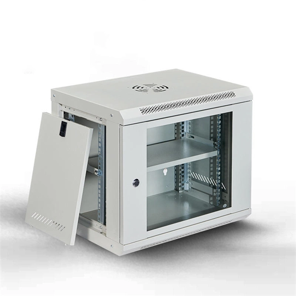
Whether upgrading an aging electrical panel or setting up your facility, this guide will walk you through the critical steps to installing an MCB Distribution Box safely. Strictly speaking, the word “Distribution Box (D-box)” can refer to two categories: electrical distribution boxes and septic tank distribution boxes. This article mainly talks about the first one. An electrical distribution box, also known as a power distribution box, panelboard, or consumer unit. These extras help make the box easier to install and maintain. Choosing the right distribution box isn't one-size-fits-all. You need to consider where it will be used, how much power it needs to handle, and how well it's built to last. Let's go through what matters most. Whether it is residential buildings, commercial facilities or industrial sites, the. This guide provides step-by-step instructions for connecting a distribution box and highlights key factors to consider during installation. It serves as a. Learn how to wire a distribution box step by step! This video shows real on-site footage of electrical installation, demonstrating safe and standardized wiring methods used by professionals.
[PDF]

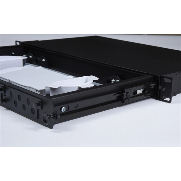
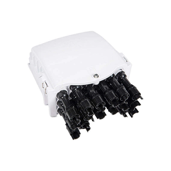
This complete guide explores everything you need to know about ODFs — from their structure, types, and key components, to installation best practices and modern design trends. Clients facing the exact demands of specialized environments—whether it's ultra-low-latency AI clusters, space-constrained military installations, or high-density telecom exchange points need more than off-the-shelf cabling. At FS, we place the customer at the heart of our operations. We are. This white paper provides a comprehensive guide to designing future-proof fiber optic networks, emphasizing a core-to-edge architectural approach. Key focus areas include backbone topologies, optical loss budgeting, standards compliance, and strategies for optimizing high-density environments like. In modern data centers and enterprise networks, Optical Distribution Frames (ODF) serve as the backbone for organizing, terminating, and managing fiber optic connections. As data centers, enterprises, telecom operators, and smart-building infrastructures deploy increasingly dense fiber links, ODFs provide the structured. Fiber optic network design refers to the specialized processes leading to a successful installation and operation of a fiber optic network. It includes first determining the type of communication system (s) which will be carried over the network, the geographic layout (premises, campus, outside.
[PDF]
Watch as we take you through the entire manufacturing process step by st. How to Make Electrical Pigtails: This is a basic tutorial on what electrical pigtails are and how to make them. Disclaimer: Always use multiple sources and do your homework before performing any electrical work. Also, make sure all work is done within national and local code. Combining is putting the layers of linerboard and medium together to form complete corrugated board. Medium is engineered to form easily into flutes as it is fed between two large gear-like rollers on the Wet End of the corrugator. Linerboard is engineered to remain flat as it adheres to the top. A corrugated box is a packaging carton made of a fluted (wavy) inner layer sandwiched between two flat sheets of paper. The thickness of the inner and outer sheets can be customized as per a brand's needs and the nature of the product. The three-layer structure creates a box that is both strong and. Pigtails act as bridges, allowing you to connect several wires to a single point without overloading connections. Professionals often prefer this method because it isolates issues, protecting downstream circuits from cascading failures. Why does this matter? Modern systems demand precision. A. The corrugated box manufacturing process involves several stages, beginning with paper rolls and ending with finished packaging boxes ready for shipment. These paper rolls are loaded onto the.
[PDF]
In fiber optics, pigtails are fusion-spliced to field fiber inside splice trays — the most common termination method in telecom and data center networks. In electrical work, pigtails connect multiple wires to a single device terminal. A pigtail is a coiled or looped section of tubing used in piping and instrumentation systems to absorb vibration, manage thermal expansion, and protect pressure instruments from direct exposure to process media. Moreover, its curved design allows it to flex under temperature or pressure changes. Pigtails play a crucial role in ensuring safe and efficient connections within electrical systems, especially when dealing with multiple wires or limited space. Understanding what a pigtail is and how it works can make your wiring projects smoother and safer. Whether you're replacing an outlet or. Whether you are a DIY or professional electrician, you will almost certainly use pigtail wires at some point in your project. This short-length wire creates something like a last mile (or last inch) connectivity to create continuity to the endpoint. And you only need a scrap wire to make this. Whether you're upgrading outlets or managing industrial circuits, these short connectors ensure power flows smoothly even when devices fail. Pigtails act as bridges, allowing you to connect. A pigtail connector is a short cable with a connector on one end and bare (stripped) wire or fiber on the other.
[PDF]

Cable Trays* — Max two 24 in. (610 mm) wide by max 6 in. (151 mm) deep open-ladder cable tray with channel-shaped side rails formed of 0. 54 mm) thick aluminum or min 0. In practice, cable tray dimensions are a system of interrelated measurements —width, depth, length, and material thickness—that directly affect cable fill compliance, heat dissipation, structural loading, and long-term expandability. From an engineering standpoint, cable tray dimensions are not. Perforated Cable Tray System expertly constructed from high-grade stainless steel, offering exceptional durability and resistance to corrosion. With side height 100mm. A properly designed and installed cable tray system will provide. Studs — Wall framing to consist of wood studs or channel shaped steel studs. Wood studs to consist of nom 2 by 4 in. Additional studs shall be used to completely frame. Best Size: Here, deep trays (75mm to 150mm) are used since power cables are typically thick and heavy. Data cables, such as your Wi-Fi or computer ones, are extremely sensitive. They do not get hot; however, they do not like to hang or sag. In case a data cable folds in an excessive manner, the. ect the minimum bend ra-dius for cables as they exit the bottom of the cable tray. A rung spacing of 6 to 9 inches (150 to 230 mm) is preferable when the cable tray cont d for instrumentation and control applications that require additional protec eferred to support and protect numerous small.
[PDF]

A ladder type cable tray tee is a fitting used to create a branch in a cable tray system, allowing cables to be routed in three directions. Its "T" shape provides a secure and efficient way to split cables from a main tray into two separate paths, ensuring organized and flexible. A cable tray tee and tee cover are components used in cable management systems to support and protect electrical and data cables. Here's a brief explanation of each:. Rigid steel cable tray tee fitting with zero tangent, safety bottom, and full accessory support. ventilation to heat producing cable such as power communication and other with the same or different width of the cable run. All fittings are available in sizes and types corresponding to the straight cable tray sections. These fitting are including: elbow, horizontal cross, vertical inside. NOTE : Equal or un equal tees can be supplied. When ordering state widths W1xW2xW3.. Office: 147/22 Nguyen Sy Sach Street, 15 Ward, Tân Binh Dist, HCMC,VN. Is it possible to connect 2 cabletrays with a "branch piece (left picture)" instead of a "tee (right picture)". The tee has 3 connectors, the branch piece only has 1 connector. I would like to ajust the "Type properties -> Fittings -> Tee" with the branch family, but can't get it accomplished.
[PDF]

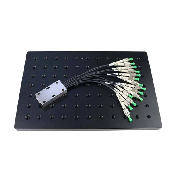
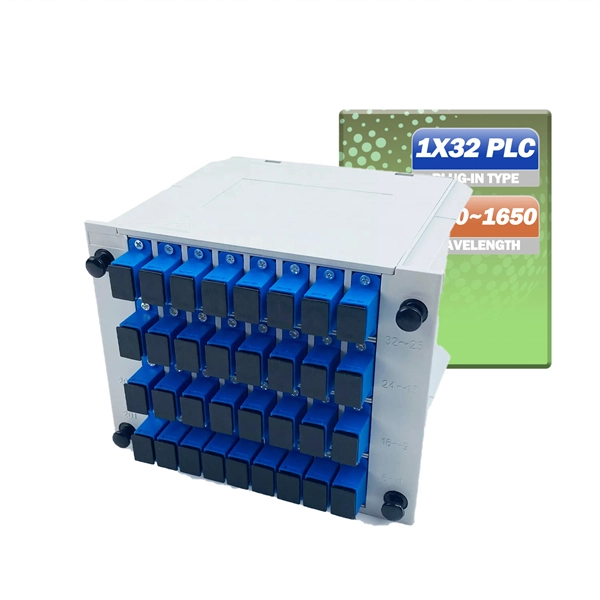
An Optical Splitter, also known as a beam splitter, is a passive optical device that divides a single input optical signal into two or more output signals. Conversely, it can also combine multiple signals into one. Knowing the difference between a splitter and an optical coupler helps you build better networks. You make your network work better when you pick the right device for each job. You can connect many users to one port with 1:n or 2:n splitters. By dividing a single optical signal from a central Optical Line Terminal (OLT) into multiple outputs for Optical Network Terminals (ONTs) at users' homes, splitters eliminate the need for dedicated fibers to each residence—slashing infrastructure costs while scaling network reach. This guide. In a Passive Optical Network (PON), a single optical fiber carries massive amounts of data using light. Signal Input: The fiber splitter receives the optical signal from the upstream network node and enters the splitter through the input fiber. Signal Distribution: Inside the splitter, according to the design structure and different. Splitters are passive optical devices that divide or combine optical signals, and they come in various types, including power splitters, uneven splitters, and wavelength-division multiplexing (WDM) splitters. Each type serves specific applications, enabling efficient use of optical infrastructure.
[PDF]
In this guide, we break down the two core stages of optical fiber manufacturing: preform production (shaping the precursor material) and fiber drawing (transforming the preform into thin, usable fiber). Explore the optical cable manufacturing process. Learn about raw materials, fiber drawing, cabling, and quality control in modern optical cable manufacturing. Is your digital life lagging? Slow streams, dropped calls? The unsung hero of our connected world, the optical cable, might be the key, and. Fiber optic cables are the backbone of today's high-speed internet, telecommunication systems, and data transfer technologies. Fiber optic technology has revolutionized the way information is transmitted, offering numerous advantages over traditional copper wiring. What makes fiber optic cables special is their ability to. The production of optical fiber is a precision-driven process that transforms raw materials like silicon tetrachloride into ultra-thin, high-performance fibers capable of transmitting terabits of data over thousands of kilometers. This manufacturing journey directly impacts the fiber's mechanical.
[PDF]
All interval wiring should conform to the relevant International Best Practices. For general site work additional precautions are necessary. Other than supplies for welding purposes, cables carrying a voltage to earth in excess of 65V should have co. All interval wiring should conform to the relevant International Best Practices. For general site work additional precautions are necessary. Other than supplies for welding purposes, cables carrying a voltage to earth in excess of 65V should have continuous metal armour or sheath which has been effectively earthed. Where trailing cables are concern. An RCD or ELCB is to be installed to all final distribution boards and tested before use on each shift. To allow only the use of 110 volt for portable electric tools. Earth Leads Earth leads must be colored yellow and green, and yellow should be of stranded copper or copper alloy with a cross section of at least 6 sq.mm. The maximum size need not e. All extension cables / cords should have a current inspection tag affixed and should be checked for damage prior to use. Extension cables / cords in one office should not be used to supply power to another office, building or adjacent offices. Cables / Cords may not run through doors, windows or ceilings unless for the purposes of temporary constru.
[PDF]