
The National Electrical Code (NEC) has established eight levels of fire resistance for fiber optic cables. These levels are based on the time it takes for a cable to burn through or melt. Corning Optical Communications manufactures quality flame retardant optical fiber cables for indoor applications, which comply with the requirements of the National Electric Code® (NEC® 2023) published by the National Fire Protection Agency (NFPA). To ensure compliance to these requirements, a. Understanding the listing requirements of fire alarm circuit cables can help you make sense of the cable alphabet soup. Here are some highlights from Part IV of Article 770. There's plenty of "expansion room" built into Article 770. Part I ends with Section 770. 44. Cabling Installation & Maintenance - Classes 1, 2, 3, and 4, communications, fire alarm, and optical fiber cables are all addressed in the NEC. By Stanley Kaufman, PhD, CableSafe Inc. UL Solutions' long-standing history in certification and Standards development makes us a trusted thought leader in the. Understanding the fire ratings and jacket options for fiber optic cables is crucial for ensuring optimal performance and safety. This technical guide will provide a comprehensive overview of these factors, their implications on cable resilience and transmission, and tips for making informed.
[PDF]

Numerical relay are embedded with specialized digital signal processor (DSP) as the computational hardware. By using DSP as the relay's processor, the relay is capable of meeting the fundamental protective requirements such as reliability, sensitivity, selectivity and speed . Thus, various protective devices are used to protect the power system, of which digital signal processor (DSP) numerical relays are capable of significantly improve protection operations. Therefore. Manuals and User Guides for Samwha DSP DSP-VIP-PM Motor Protection. We have 1 Samwha DSP DSP-VIP-PM Motor Protection manual available for free PDF download: Manual Samwha dsp DSP-VIP-PM Motor Protection Pdf User Manuals. View online or download Samwha dsp DSP-VIP-PM Motor Protection Manual. Many of the new protection relays are microprocessor based and are generally referred to as numerical relays. This means that signals from transducers are sampled at fixed time intervals, digitally encoded, and processed by equipment which resembles a computer to derive relaying information, e.
[PDF]

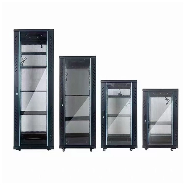
Cable trays play a key part in keeping fire protection systems working. Here is what they do: They Make Safe Paths for Fire System Wires Cable trays are made from materials that resist fire. They can help stop fire from spreading. Recognize electrical cable tray misuse that can lead to electric shock and arc-flash/blast events and fires caused by overheating. The use and installation of cable trays is covered by legally enforceable OSHA regulations in 29 CFR 1910. 305(a)(3), or comparable standards promulgated by States. Scope: Firestopping for busway, cable trays, cables, and trunking passing through walls in enclosed electrical installations. Where cables pass through shafts, walls, slabs, or enter electrical panels or cabinets, openings shall be tightly sealed with firestopping materials in accordance with. Cable trays can be part of a planned cable management system to support, route, protect, and provide a pathway for cable systems. Power, low voltage control, data, or telecommunications wiring distribution systems can be used with cable trays. 1 This section applies to cable trays utilized to support and route low voltage cables (telecom, security, A/V). No fire alarm cables will be permitted to be installed in cable trays. If a fire starts, the tray protects the wires inside from flames and.
[PDF]
The global protective relay market size was worth more than USD 2. 82 billion in 2025 and is poised to witness a CAGR of over 5. 5%, crossing USD 4. 82 billion revenue by 2035, fueled by rising integration of digitalization & IoT in protective relay. The global market for Protection Relays was valued at US$ million in the year 2024 and is projected to reach a revised size of US$ million by 2031, growing at a CAGR of %during the forecast period. A protection relay is a smart device that receives inputs, compares them to set points, and provides. The Protective Relay Market was valued at USD 3. 9% through 2024 to 2030, reaching nearly USD 3. 4%, according to Strategic Market Research. Protective relays are essential components of modern power systems. The Protection Relays Market encompasses the design, manufacturing, and deployment of electromechanical, solid-state, and digital relays that monitor electrical systems for faults or abnormal conditions and initiate protective actions.
[PDF]
The original unstructured record data for the defect of the relay protection devices (RPDs) may contain problems influencing the data mining, and it is lack of quantitative evaluation. So the purpose of this.
[PDF]

Generator protection relays are devices that detect abnormal operating conditions and isolate the generator from the system to prevent damage. These relays act as the first line of defense and are installed with strict adherence to IEC Standard for Protection Relays. Protecting generators from different electrical, mechanical, and thermal stresses is known as generator protection. To safeguard machines from overloads and unusual circumstances, preventive measures are required. Faults are inevitable even with effective design, construction, and operation. Below is an overview of the different types of relays used in generator systems, their functions, and their specific applications. Electromagnetic relays use. Generator Protections are broadly classified into three types: Class A, B and C. Class A covers all electrical protections for faults within the generating unit in which generator field breaker, generator breaker and turbine should be tripped. What Are Generator Protection Relays? Generator protection. There are various protection relays and those are used for protection against a wide variety of conditions. The fundamental principles that are covered in this course are equally applicable to. IEEE C37. 2 defines the IEEE “numerical” function designation for all protective relay functions. This presentation primarily uses the designations from the Beckwith M-3425A relay, which in most cases follows IEEE C37.
[PDF]
Thermal relays are the perfect solution for providing protection to motors which provides the most precise tripping for the electric motor during single phasing and overload. This article discusses an overview.
[PDF]

A new updated course will be released for sale during the spring of 2026. SFS 6002 Electrical safety -course is mandatory in Finland for all persons involved in electrical works: installers, managers, assistants etc. The course is valid for 5 years and shall be renewed to maintain the. Electrical qualification 1 (Electrical Safety Act 1435/2016 Section 66) The holder of electrical qualification 1 may work as an electrical work supervisor and supervisor of operations in all electrical and operational work. These regulations lay down binding requirements, which cover e. A person who builds, repairs or maintains electrical installations, or repairs and maintains electrical appliances must be professionally qualified, and Tukes must be notified before any such operations begin. The operators are called electrical or lift contractors. A company or a natural person. Electrical safety is not just a legal requirement – it's part of everyday workplace safety. Cad Sä Oy has developed the Electricity Passport, a new training model in which SFS 6002 training is carefully tailored to the specific electrical tasks each participant will perform in their project. The. Finnish electrical safety card (Sähkötyöturvallisuuskortti SFS 6002) is intended for people working in the maintenance and servicing of electrical installations, machines and equipment up to 1000 V in Finland.
[PDF]

Protect fiber optic cable connections:The joint box provides physical protection for the fiber optic cable connection parts to prevent damage to the fiber optic cable caused by external environmental factors such as moisture, dust, chemical corrosion and mechanical damage. Provide a stable. Fiber optic sleeves are protective devices used for fiber optic connections. Splice protection sleeve, usually made of plastic or metal, are used to secure and protect the fusion joint between two optical fibers. Fiber Cable Joint Box is attributed to the mechanical pressure sealing joint system. Fiber Cable Joint Box is a continuous protection device for supplying optical, sealing and mechanical strength continuity between adjacent optical. The optical fiber terminal box is the terminal joint of an optical cable, one end of which is an optical cable, and the other end is a pigtail, which is equivalent to a device that splits an optical cable into a single optical fiber. The user optical cable terminal box installed on the wall, its. Fiber Optic Splice Closure is designed to protect optical fibers from debris, dirt, dust, moisture and water. As much of the fiber system is outside in a harsh environment, these fiber optic splice closures are designed to meet the tough protection requirements of fiber-optic splices. UnitekFiber. Overview Application of Optical Fiber Splice Closure/Joint Box/Joint Closure: 1. CATV environment.
[PDF]

This certification requires completion of the following two courses, which may be completed in any order within an 18-month period: National Electrical Code 2020, 4 days, 2. 8 CEUs, which you can take In-Person or Virtual, Live. Electrical Safety for Inspectors, 4 days, 2. After completion of all requirements you must submit your certification application. Your certification package will include a certificate and laminated wallet card. {{$pageCtrl. description}}. General requirements for certification include passing an exam or exams, specific industry related experience, successful performance of key role specific activities, and personal recommendations (Levels III and IV). Once earned, certification must be maintained through Continuing Professional. Whether you specialize in fire protection systems, building and life safety, or electrical, our acclaimed certification programs can help verify your competence and set you apart from your peers. Empowering employees to work safely and effectively with Megger's offering of courses and certification programs in electrical maintenance, electrical safety, as well as through our custom-tailored training. Copyright © 2026 Megger, all rights reserved. Participants gain practical experience with real-world equipment, learning to interpret.
[PDF]

This article describes the anti-pumping relay, its definition, function, and circuit diagram. In a circuit breaker it is desired that when close and trip operation is performed on the circuit breaker with the closing coil energized, the subsequent closing operation should be prevented. So let's. Anti-Pumping relay is nothing but a NO contact, which means when the circuit breaker in closed condition the relay will be as NO point and if the circuit breaker in open condition the relay will be as NC Condition. The anti-pumping relays is connected in series with the circuit. An anti pumping relay (also called antipumping relay or Y-relay and ANSI 94 Trip or Trip-Free Relay) is a protective device that prevents a circuit breaker from closing repeatedly when a continuous close command is present. In simple terms, it stops your circuit breaker from “pumping” – which means. Anti-pumping relays are used in circuit breakers to prevent the breaker from closing unexpectedly after tripping. If the TNC switch fails (Trip normal close) or there is any problem with the CB (circuit breakers) closing circuit, the continuous CB (circuit breakers) close command can be extended to. Why is the Anti-Pumping Relay Used? A circuit breaker is a very important equipment for a high-voltage power system. It protects the system from high current or voltage during a faulty condition.
[PDF]

Arduino Safety Relay Box With Wall Socket : A relay is an electrically operated switch. In this project there is no real need to isolate one circuit. Relay rooms are essential in modern commercial or industrial buildings, serving as secure enclosures for electrical relays that manage power distribution and automation systems. Designing a relay room requires balancing technical precision with safety, efficiency, and future scalability. Many relays use an electromagnet to mechanically operate the switch and provide electrical isolation between two circuits. In this article, you will learn how to design an electrical control cabinet for optimal safety and efficiency, following some. This handbook covers the code of practice in protection circuitry including standard lead and device numbers, mode of connections at terminal strips, colour codes in multicore cables, dos and donts in execution. Reliable components ensure system faultlessness and durability. Modern design and user-friendliness. equipment of most. This is Part 1 in a series of tutorials that will show you how to build a Bussmann RTMR fuse/relay block. If you're not familiar with this product, it's a simple waterproof enclosure that allows you to connect accessories on your vehicle through relays and/or fuses. After reading this tutorial, you.
[PDF]
At the heart of every optical transceiver lie three essential components, often called the “Three Pillars” of optical communication: Laser — generates light. Modulator — encodes data onto the light. Photodiode — decodes light signals back into electrical form. An optical receiver is a device that converts light signals traveling through fiber optic cable back into electrical signals that electronic equipment can process. The core function of the optical receiver relies on a physical phenomenon known as photoelectric conversion. When a modulated light signal. The polarization independent isolator is made of three parts, an input birefringent wedge (with its ordinary polarization direction vertical and its extraordinary polarization direction horizontal), a Faraday rotator, and an output birefringent wedge (with its ordinary polarization direction at. Our optical receivers and detectors make photodetection easy and provide the lowest noise and cleanest response possible. Our broad offering spans wavelength ranges from UV to short-wave IR for free-space and fiber-coupled configurations in many versions: high-speed, general-purpose, balanced. Optical receivers are devices that convert light signals into electrical signals using photodetectors, which come in various types such as photodiodes and avalanche photodiodes. The document covers key concepts such as the operating principles of these detectors, noise types, signal-to-noise ratio.
[PDF]
Typically, an optical circulator consists of three main parts: wave plates, Faraday rotators, and birefringent crystals. When light enters the circulator, it is split into two beams with orthogonal polarization states. An optical circulator is a non-reciprocal device that directs light signals sequentially between multiple ports. You can think of it as a traffic controller for light, ensuring signals flow in one direction without interference. Unlike optical isolators that block reflected light, a circulator routes optical signals in a specific order — typically Port 1 → Port 2 and Port 2 →. An optical circulator is a three- or four-port optical device designed such that light entering any port exits from the next. This means that if light enters port 1 it is emitted from port 2, but if some of the emitted light is reflected back to the circulator, it does not come out of port 1 but. Optical Circulators are crucial components in modern optical communication systems, enabling the efficient routing of optical signals between different ports. In this comprehensive guide, we will explore the definition, basic principles, and importance of Optical Circulators, as well as their. The optical circulator is a fundamental device, acting as an advanced traffic controller that provides strict directional control over light signals within the network architecture.
[PDF]
In electric power systems and industrial automation, ANSI Device Numbers can be used to identify equipment and devices in a system such as relays, circuit breakers, or instruments. The device numbers are enumerated in ANSI/IEEE Standard C37.2 Standard for Electrical Power System Device Function Numbers, Acronyms, and Contact Designations. Many of these devices protect electrical. List of device numbers and acronyms• 1 - Master Element• 2 - Time-delay Starting or Closing Relay• 3 - Checking or Interlocking Relay, complete Sequence• 4 - Master Protective. A suffix letter or number may be used with the device number; for example, suffix N is used if the device is connected to a Neutral wire (example: 59N in a relay is used for protection against Neutral Displacement); and suffixe.
[PDF]


