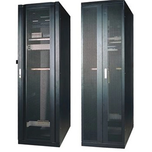
Huawei MA5683T is an aggregation Optical Line Terminal (OLT), it supports up to 6 service slots and can support a maximum of 12,000 subscribers (GPON). MA5683T has GICF/X2CS Uplink Board available for selection, and two power slot redundancy for DC power input. Ethernet link aggregation increases link bandwidth by bundling multiple physical links to form a logical link. Link aggregation can work in manual mode or Link Aggregation Control Protocol (LACP) mode. In manual mode, you must manually create an Eth-Trunk and add member interfaces to the Eth-Trunk. As shown in Figure 1, SwitchA and SwitchB are connected to the networks of VLAN10 and VLAN20, respectively, via Ethernet links, and there is a large amount of data traffic between SwitchA and SwitchB. Link aggregation has the following advantages:. Original operating mode: Two S5700s were configured with Eth-Trunk1, and the ports of the three lines that need to be communicated were added to Eth-Trunk1. Set the port to access to allow the corresponding VLAN to pass; so that the two floors of the network can communicate normally In this way. And there are two link aggregation types. In LACP mode, there are active and backup links and backup links are used for redundancy. For this example, we. Link Aggregation is a technology defined in IEEE 802. It enhances bandwidth, provides fault tolerance, and allows load balancing between connected devices. Key benefits of link aggregation: Higher.
[PDF]
The Huawei S5731-S24T4X is a switch from Huawei's S5731 series, designed for enterprise networks. It is a versatile and high-performance device that supports a range of applications, including data center, campus, and branch networking. The Xingmai Passive Ethernet Network (PEN) is an all-optical campus network solution based on the passive technology. Leveraging mainstream Ethernet protocols, the Xingmai PEN solution uses optical fibers to implement passive data transmission without the need of any ELV room. 24 Gigabit Ethernet Ports: Provides 24 10/100/1000 Mbps. Demand for Wi‑Fi 6-ready campus networks is growing rapidly, the Huawei S5732 Series empowers modern networks as a cutting-edge Aggregation Switch and Campus Switch, offering multi-Gigabit access, PoE++, and service intelligence. Its capabilities—from built-in WLAN AC to VXLAN and MACsec—ensure. CloudEngine S6780-H series switches are Huawei's next-generation enterprise-class core and aggregation switches that provide 64 x 100GE/32 x 25GE ports and 16 x 400GE optical ports. CloudEngine S5732-H hybrid optical-electrical.
[PDF]
They support link aggregation protocols such as Link Aggregation Control Protocol (LACP) and Static Link Aggregation, which allow multiple physical links to be combined into a single logical connection. This enhances bandwidth, redundancy, and ensures failover capability in case of a. The three layers of a traditional three-layer network design are the core layer, aggregation layer, and access layer. Together, these layers can offer consumers a network that is safe, reliable, and affordable. As the physical part of the aggregation layer, aggregation switches typically play a. An aggregate switch is a high-capacity network switch that consolidates connections from multiple access switches, acting as a central point for managing network traffic and providing enhanced bandwidth capabilities. It is essential for larger networks requiring efficient data flow. This article looks at what each such tool does, compares how they differ from each other, and offers suggestions as to what sort of network each. The aggregation (sometimes also called distribution) layer is a real crossroad. Its primary goal is to increase network scalability by providing a single place to interconnect multiple access switches and the core layer.
[PDF]
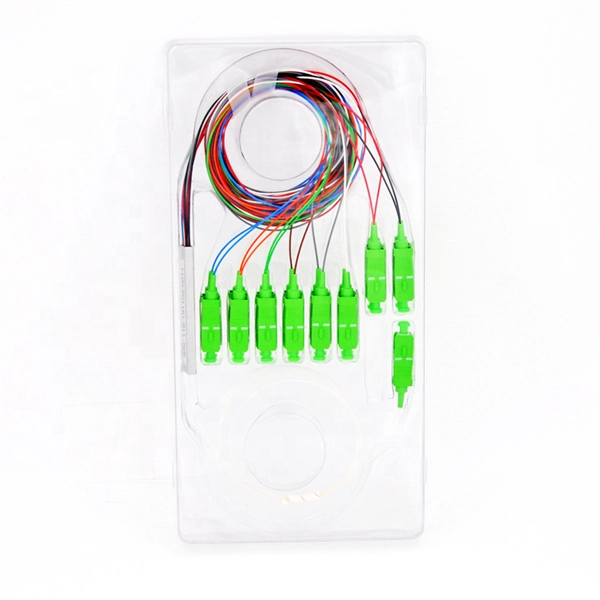
The splitters distribute the optical signal to multiple fibres without affecting the wavelength. Splitter 1:32 based on Planar Waveguide technology where the light is guided through waveguides in a substrate. The waveguides are branched out according to how much the light should be. Beamsplitters are optical components used to split input light into two separate parts. Beamsplitters are common components in laser or illumination systems. Beamsplitters are also ideal for fluorescence applications, optical interferometry, or life science or semiconductor instrumentation. Light. Thorlabs offers a wide range of optical beamsplitters. Our plate beamsplitters have a coated front surface that determines the beam splitting ratio while the back surface is wedged and AR coated in order to minimize ghosting and interference effects. Operative wavelength: 1260 - 1620 nm. The split ratio of light transmittance and reflectance is 1:1 and is called a half mirror. Good fit for large beam size applications at a reasonable price. Advantages are: minimal. Use this beam splitters buying guide to compare major types, define selection criteria, and find suppliers: Professional purchasing of high-value photonics products is a substantial responsibility, where a structured decision-making process is essential. PLC Splitters are available with 900µm loose tube.
[PDF]

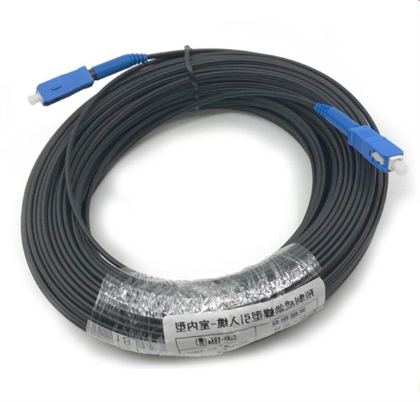
Use two fibers: one dedicated to TX, the other to RX. Both sides transmit and receive at the same wavelength (common values: 850 nm MM, 1310 nm/1550 nm SM). The front panel is usually labeled TX and RX, and you cross-connect TX→RX, RX→TX with a duplex patch cord. Switch optical port intercommunication means that the optical fiber ports of two switches are connected to each other to achieve the purpose of network connection. The connection between two or more Ethernet switches in a certain way (Uplink port, etc. ) is called the cascade. SFP modules insert into these slots and and require two strands of fiber, typically duplex Using multi mode fiber (for runs under 1000 feet) or duplex single mode fiber (for runs over 1000 feet). This is a cost-effective and high performance way to connect network switches. Use one fiber strand for both. The switch supports 10 Mbps, 100 Mbps, and 1000 Mbps connections. Using Gigabit Ethernet (1000 Mbps), the switch sends files across the network at speeds up of to 2000 Mbps due to the full-duplex nature of Gigabit Ethernet connections. You can either connect 24 Ethernet copper cables or 22 copper. Port types are limited to two: optical and Ethernet. Optical ports on switches typically accommodate optical modules for transmitting data via fiber optic cables. In situations where there's a shortage of Ethernet ports, some users may insert Ethernet port modules into optical ports to connect with.
[PDF]
This video makes connecting your fiber optic cable to your router a breeze! We'll guide you through the entire process step-by-step, ensuring a smooth and hassle-free experience. Our Experts are helping user's, who are facing issues with their tech gadgets like. In this guide, we'll walk you through how to connect a fiber optic cable to a router safely and efficiently. Why Use Fiber Optic Internet? Before diving into the setup, let's quickly recap why fiber optics are worth the effort: Lightning-fast speeds (up to 1 Gbps or higher). Low latency for. Connect an Ethernet cable from the WAN port of your router to a LAN port on the Internet source (such as a broadband modem or fiber-optic modem). If you. This conversion happens either through an Optical Network Terminal (ONT) or directly via specialized router ports. Check compatibility: Before you begin, make sure your router supports fiber optic connection. Not all routers can connect directly to a fiber cable, so it is important to verify this information before continuing. Here's a step-by-step guide to help you through it. Understand the Basics Before diving in, familiarize yourself with the components involved:.
[PDF]
Step 3 Remove the cables or optical modules from the old card. Press the two green locking clips in the middle of the card to eject the ejector levers. Turn the ejector levers outward and slowly pull the card out. Place the replaced. Unplug the optical fibers from the optical module before removing it. Install or remove optical fibers carefully to avoid damaging the fiber connectors. If an optical module cannot be completely inserted into an optical. Page 7 Optical port USB storage device Wi-Fi terminal 1. Wear an ESD wrist strap or ESD gloves when replacing the optical module. Therefore, replace an optical module only when you confirm.
[PDF]
Locate your ONT/ONU: This is typically a small box provided by your ISP, often located near where the fiber optic cable enters your home. Connect the fiber optic cable: Plug the fiber optic cable from your ISP into the designated port on your ONT/ONU. This is usually clearly labeled. However, setting up a fiber optic connection to your router can seem daunting if you're unfamiliar with the process. In this guide, we'll walk you through how to connect a fiber optic cable to a router safely and efficiently. Why Use Fiber Optic Internet? Before diving into the setup, let's quickly. To set up your router for fiber internet quickly, connect the router to your fiber modem, access the router's settings via a web browser, and input the provided ISP credentials. Make sure to update the firmware, configure Wi-Fi security, and customize your network name for optimal performance. With. Setting up a fiber internet connection requires understanding key hardware components and following a specific connection sequence to establish your home network. Here's a simple guide to help you through the process: 1. Check Your Fiber Optic Equipment Before you start, make sure you have the necessary equipment: Fiber Optic Modem (ONT – Optical Network Terminal):.
[PDF]

The WannaCry ransomware attack was a worldwide cyberattack in May 2017 by the WannaCry ransomware cryptoworm, which targeted computers running the Microsoft Windows operating system by encrypting data and demanding ransom payments in the form of bitcoin cryptocurrency. It was propagated using EternalBlue, an exploit developed by the United States National Security Agen. DescriptionWannaCry is a , which targets computers running the by encrypting (locking) data and demanding ransom payments in the. The attack began on Friday, 12 May 2017, with evidence pointing to an initial infection in Asia at 07:44 UTC. The initial infection was likely through an exposed SMB port, rather than as initially ass. Linguistic analysis of the ransom notes suggested the authors were likely fluent in Chinese and proficient in English, as the versions of the notes in those languages appeared to be human-written while the rest seeme. The ransomware campaign was unprecedented in scale according to, which estimates that around 200,000 computers were infected across 150 countries. According to, the four mo.
[PDF]
The SFP port is commonly found on Gigabit Ethernet switches and is primarily used for fiber optic device connections or for uplinking 1G switches to aggregation/core layer devices, providing higher-bandwidth links. You can add a compatible SFP transceiver module to the SFP port of. SFP ports enable Gigabit switches to connect to a variety of fiber and Ethernet cables and extend switching functionality throughout the network. Small form-factor pluggable is a hot-swappable interface used to connect network and storage switches and transfer data. Switches with SFP ports can. Choose an SFP module based on the fiber optic cabling that will be connected to the network switches. SFP transceiver modules almost always require two fiber optic cable strands. In this guide, we'll cover the following: What is an SFP port? Why is the SFP port important? SFP vs. QSFP28. Enterprise LANs use the RJ45 port on 100/1000BASE switches. It connects access layer devices and uplinks from desktop switches or directly to end devices. RJ45 ports remain essential for. An SFP switch uses Small Form-Factor Pluggable (SFP) modules to form a network switch for high-speed connectivity between devices. These interchangeable modules support various media types, including copper or fiber-optic cables, providing flexible networking options based on specific requirements.
[PDF]
With up to 48 10 GE downlinks and 40/100 GE uplinks, the S6730‑H series supports bandwidth-hungry access and spine layers—perfect for Wi‑Fi 6 APs, 4K/8K video, and virtualization workloads. Based on Huawei's VRP OS, the series delivers OSPF, BGP, RIPng, IS‑IS, VRRP, and. This document provides campus networks typical configuration examples and feature typical configuration examples. "Campus Networks Typical Configuration Examples" provides typical campus network networking modes and a variety of deployment examples. Positioned perfectly as an Aggregation Switch or Core Switch, the S6730‑H delivers scalability, security, and cost-effectiveness for modern digital. The S5730-SI series switches are next-generation standard gigabit Layer 3 Ethernet switches. They can be used as access or aggregation switches on a campus network or as access switches in a data center. It also provides enhanced Layer 3 features and mature IPv6 features. eKitEngine S530 switches can be use in various scenarios. The S3700 utilizes cutting-edge hardware and Huawei Versatile Routing Platform (VRP) software to provide high-performance access and aggregation to an enterprise campus network.
[PDF]
The layer 2 switches prevent over-crowding of data packets in transmission links and access devices. · Layer Positioning: The data link layer (Layer 2) of the OSI model, realizing local forwarding of data frames based on MAC addresses. · Core Task: Establishing direct interconnections between devices within a local area network to ensure efficient communication within the same network segment. ·. The core layer is the backbone of the network. It provides a high-speed connection between different distribution layer devices. The distribution layer connects the access layer to the core layer. When designing a campus LAN, you may. In enterprise networking, the hierarchical three-tier model is divided into three distinct roles: access switches (which connect end-user devices to the network via Layer 2), distribution switches (which route inter-VLAN traffic and enforce security policies at Layer 3), and core switches (which. The core switch is the most important piece of hardware in this infrastructure, acting as the high-speed, central nervous system that ensures all parts of the network can communicate. The core switch functions as the central point of the entire network, forming the high-speed backbone for the. Distribution Layer: The distribution layer is an intermediate layer. Simply put, it's the kingpin that keeps your network humming. You may also want to know: Can a Nintendo Switch Play DS Games? ·.
[PDF]

There are 48 bicolor LEDs (green/amber) for the first 48 SFP+ ports and 16 tricolor LEDs (green/amber/white) for the SFP-DD ports. The last set of LEDs pulse once in white before indicating the FC port status in green or amber. When it blinks white twice, it shows the status of the second port of the SFP-DD. The port status LEDs for the FC ports are arranged left and right to correspond to the upper and lower ports respectively in each pair. LEDs on the port side of the switch Table 1. LEDs on Cisco Catalyst 9500 Series Switches 1 Available only on switches with 10G ports. System LED Indicator System is not operational. System is operating normally. As a group or individually, the LEDs show information about the switch and about the ports Preventing Overload - Each port that provides PoE has a maximum power it can deliver. Three LEDs are used on each port. Ports on the Cisco Catalyst switch do not have LEDs. Not the question you're searching for? Each. Number of LEDs per port - Ports that cannot be split; for example, 1G ports must have 1 LED per port. Location - A port LED should be placed right above the.
[PDF]
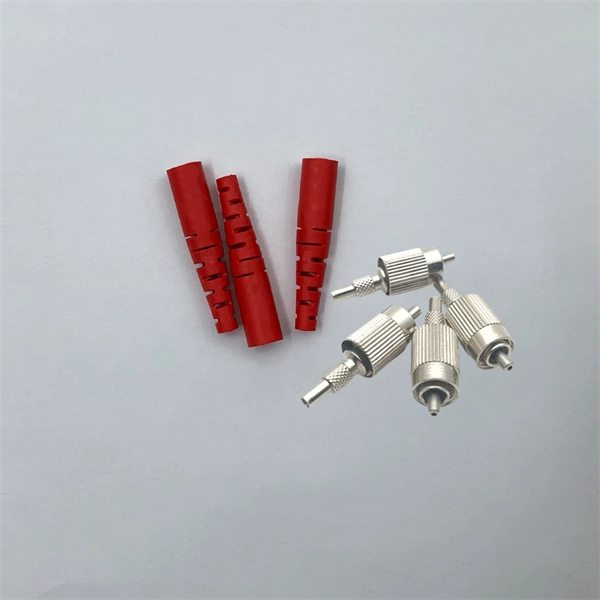
Pigtail, also known as pigtail, has only one end with a connector, and the other end is a broken end of a fiber optic cable core. It often appears in fiber optic terminal boxes. (couplers, jumpers, etc. are also used between. Long tail fibers consist of a phage-proximal and a phage-distal rod, each around 80 nm long and attached to each other at a slight angle. The phage-proximal rod is formed by a homo-trimer of gene product 34 (gp34) and is attached to the phage-distal rod by a monomer of gp35. are also used between them). One. The tailed phage T4 encodes a specialized device for this purpose, the long tail fiber (LTF), which allows the virus to move on the bacterial surface and find a suitable site for infection. Consequently, the infection efficiency of phage T4 is one of the highest, reaching the theoretical value of. Bacteriophages, often called phages, are viruses that infect and replicate within bacteria. These tiny biological entities play a significant role in microbial ecosystems. Tail fibers are structures on the phage that mediate their initial interaction with bacterial hosts, allowing them to recognize. The tail (Fig. Infection is initiated with the reversible attachment of six long tail fibers (LTFs) to the cell's outer layer of lipopolysaccharides, followed by transformation of the.
[PDF]

Wavelength: 1310nm, 1550nm, or CWDM/DWDM wavelengths. LR (Long Range): 10km, 1310nm, Blue latch. Each SFP module operates at a specific wavelength, and to avoid confusion, manufacturers use color-coded pull rings for easy identification. Here's a quick guide: 🔹 850nm (Black) – Short-distance multimode fiber (up to 550m) 🔹 1310nm (Blue) – Longer reach, typically used for single-mode fiber (up. Wavelength division multiplexing modules differ from other optical modules in center wavelengths. Wavelength division. Coarse Wavelength Division Multiplexing (CWDM) SFP modules are a practical and cost-effective solution for expanding network capacity while keeping equipment simple and scalable. Selecting the right wavelength for CWDM SFPs is essential to ensure optimal performance, minimal interference, and. Every optical transceiver operates at a specific wavelength, typically measured in nanometers (nm). Their pull. SFP (Small Form-factor Pluggable) is a compact, hot-swappable module used in network devices such as switches, routers, and servers to provide network connectivity and is widely used in network communications. Think of it as the “translator” for your network equipment, converting electrical signals into optical signals.
[PDF]