In practical applications, there are many electrical connection methods for industrial power distribution boxes, which will be introduced below. Primary distribution systems consist of feeders that deliver power from distribution substations to distribution transformers. Many feeders leave substation in a concrete ducts and are routed to a nearby pole. At this. Proper sub panel wiring is a fundamental skill for any licensed electrician, critical for safely expanding a building's electrical capacity. The process involves installing a secondary breaker panel fed from the main service panel. Key compliance points include performing an accurate panelboard. Four basic circuit arrangements are used for the distribution of electric power: radial, primary selective, secondary selective, and secondary network circuit arrangements. A busbar is a large-section conductive. The Secondary Distribution Box (SDB) receives power from Main Power Distribution box via an extender cable and provides a central power distribution to feed normal branch circuits to the electric floor modules through snap-on extender cables. The SDB can be fitted with terminal blocks for custom. Small electrical installations normally have only one distribution board, connected directly to the main service, and appliances are powered with branch circuits protected by breakers. However, powering all loads from the same distribution board is impractical in larger installations, since the.
[PDF]

Fiber optic connectors can be categorized according to different standards such as utilization, fiber count, fiber mode, and transmission method. They are also divided into single-mode and multimode types based on their distinct characteristics. This guide will walk you through the most common fiber connector types, explaining their characteristics, advantages, and typical use cases. Whether you're planning an FTTH deployment, upgrading a data center, or working in telecom infrastructure, this guide will help you make informed decisions. Compared to Copper cables, Fiber connector types are incredibly varied. Where copper twisted pairs tend to terminate with an RJ45 plug, fiber optic connectors come in all sorts of shapes and sizes, with all manner of different use cases in mind. An optical fiber connector is used to join optical. With a wide variety of connector types available, choosing the right connector for your network can be challenging. Learn how each connector works, where it's used, and how to choose the right option for today's high-density, high-speed networks. It is a precise coupling device that joins fiber optic cables quickly, enabling faster connection and disconnection than splicing. The connector mechanically orients the fiber cores, allowing light to pass and travel through. In this guide, you'll explore various types of fiber optic cable connectors, each with unique features and best uses. We'll also provide practical advice.
[PDF]
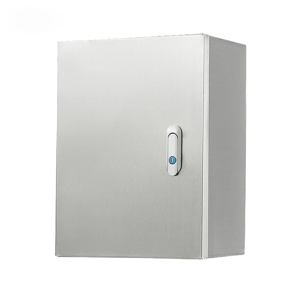
Attach a ground wire from one of the threaded studs (A) at the bottom of the housing, to the mounting plate (B). The ground resistance between all system parts shall be < 0. Learn how to install a distribution box safely and correctly. Covers wiring, placement, standards, and expert tips for a compliant setup. It takes the incoming power and safely distributes it to different circuits throughout your building. In modern electrical systems, cable distribution boxes (also known as electrical distribution boxes or distribution boxes) play a crucial role as the key hub for managing, distributing, and protecting circuits. Whether it is residential buildings, commercial facilities or industrial sites, the. A well-chosen and properly installed distribution box can prevent electrical hazards, reduce downtime, and ensure your electrical system operates smoothly for years to come. Let's explore how these critical components work and why they deserve your attention. Ensuring a fixed connection prevents mechanical vibration and maintains the integrity of the internal components. This guide focuses on technical installation.
[PDF]
In this video, we'll walk you through the process of wiring a home distribution box with a detailed connection diagram. Whether you're an electrician or a DIY enthusiast, this guide will help you understand the basics of home electrical distribution. more Welcome to. This guide provides step-by-step instructions for connecting a distribution box and highlights key factors to consider during installation. What Is a Distribution Box? A distribution box, also known as an electrical distribution board, is a critical component in electrical systems. A distribution board or distribution box is where the main power supply is distributed to multiple loads. In this article, I'll teach you how to wire a Power Distribution Block (PDB) to distribute electricity from a single input source to multiple pieces of equipment in your branch circuit.
[PDF]
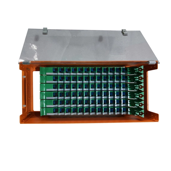
In network cabling, outdoor connections generally use fiber optic cables. When these optical fibers are installed or laid out, a Fiber Termination Box, or FTB, is used to distribute and protect the optical fiber link.
[PDF]
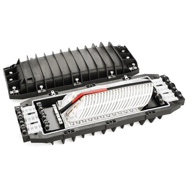
The 2 port surface mount fiber enclosure serves as termination point designed to joint drop cable and pigtail in home or office for wall mout or suface mount installation. It fully supports mechanical/fusion splicing, termination, and cable mangement within a single, compact indoor unit. The. The fiber panel box provides superior protection as the main function of the panel is to fix the module, protect the cable at the information outlet, and play a role similar to a screen. The fiber optic terminal junction Box solid in construction,with porcelain white finish. The fiber splicing, splitting, distribution can be done in this box, and meanwhile it provides solid protection and management for the FTTx network building. Modern telecommunications depend on 2 core connection box as basic building blocks for fast data transfer over great distances. These devices and systems use light to transport data and provide better dependability and bandwidth than conventional copper connections. They are indispensable in many. The 2 Cores Fiber Distribution Box (FDB-102A-1) IP-55 SC Connector PLC Splitter is a compact and rugged outdoor enclosure designed to provide a safe and secure environment for fiber optic cables and splices. Copyright 2024 FOCC All trademarks, products, and company names mentioned are the property. Product added! Browse Wishlist Max. Inlet Cable Diameter Max.
[PDF]
Picking up the best router for fiber internet isn't just about going to the market and choosing one of the best wireless routers. Instead, you need to carefully look at its specs, performance, and the type of securit.
[PDF]
This schematic details the products and procedures for the treat-ment of construction joints/cold joints in new concrete structures. Cold joints occur when a fresh concrete batch is poured against a partially hardened existing layer. As you know, concrete hardens through chemical reactions between cement aggregate, water, and air. This detail uses two elements in addition to ad-ditives and coaings to waterproof. Cold jointing concrete is a technique used to connect two separate concrete pours that have not fully bonded together, often due to delays or interruptions in the pouring process. This method involves preparing the existing concrete surface by cleaning and roughening it, applying a bonding agent to. Eng-Tips is the largest forum for Engineering Professionals on the Internet. Members share and learn making Eng-Tips Forums the best source of engineering information on the Internet! Congratulations GregLocock on being selected by the Eng-Tips community for having the most helpful posts in the. Managing cold joints is an important concept to grasp when working on concrete projects. For the completed structure to be strong and long-lasting, cold joints must be handled correctly. The term "cold" is used because the two concrete layers are not bonded properly, which can result in a weakened.
[PDF]
Follow these steps to connect your WiFi router or modem using the TP-Link TL-POE10R POE Splitter: Plug one end of a Cat6 Ethernet cable into a POE port on the POE switch. This cable will carry both data and power. Connect the other end to the Ethernet input port of the TP-Link POE. We can use TL-POE150S and TL-POE10R to expand the network for the place where power line can not reach or there is no outlet. In the topology shown as above, both TL-POE10R and the device which connect to it do not need external power adapter, the TL-POE150S can provide power supply and data for. In this video, we dive into how to use the TP-Link TL-POE10R POE Splitter to supply power and LAN connectivity to a WiFi router, modem, or access point from a CCTV system POE switch. This powerful device simplifies your network setup by delivering both power and data through a single Ethernet. Connecting TP-Link cameras to a POE switch is a seamless, plug-and-play process that powers and networks your security system in minutes. Simply link the camera to the POE switch using a single Ethernet cable—handling both data and power—then configure via the TP-Link app for live viewing and. The Injector sends power and data over the Ethernet cable to the Splitter. Then the Splitter separates the data and power back into two cables and delivers them to the remotely located access point or other network device that requires a 5/9/12-volt power input. 2 Features Complies with IEEE.
[PDF]
This map shows where fiber internet service is available across the United States from all providers. Use the map controls to color by number of fiber providers or by maximum fiber speed available. Fiber-optic internet is the fastest and most reliable type of internet connection available. It uses. Fiber internet is a broadband connection that runs on light signals from fiber-optic cabling, delivering multi-gig upload and download speeds. Fiber is available. Spectrum uses a Fiber broadband network, nationwide 5G and Advanced WiFi to keep you connected. Spectrum delivers dedicated Fiber Internet backed by our industry-leading 100% uptime SLA guarantee. Spectrum Fiber-Powered Internet delivers the fastest and most reliable internet experience for your. If Verizon Fios is available at your location, select the plan that best meets your needs: 300 Mbps: More than enough bandwidth for the average household—you can easily stream (including 4K video), game and make video calls on multiple devices at once. Tired of spotty internet connection? Enjoy high-speed fiber-optic internet with up to gigabit speeds, no annual contracts, and an included Wi-Fi 6 router. Try T-Mobile Fiber.
[PDF]

On this page you will learn what differentiates a PoE enabled switch from a regular LAN switch, when you should use a PoE switch versus a PoE injector and, what exactly is PoE (Power over Ethernet) technology. A PoE switch simplifies network installation by providing power and data transmission over a single Ethernet cable. However, to take full advantage of a PoE switch, it's crucial to understand how to use it properly. In this blog, we will guide you through the key steps to ensure a successful PoE. A PoE (Power over Ethernet) switch is a network switch that delivers both power and data through a single Ethernet cable to connected devices such as IP cameras, VoIP phones, wireless access points, and IoT devices. PoE Switches - what are they, when to use them, what to know about them, and when not to. Written by Don Schultz, trueCABLE Senior Technical Advisor, Fluke Networks Copper/Fiber CCTT, BICSI INST1, INSTC, INSTF Certified You just bought a nice PoE (Power over Ethernet) switch with cameras and access points. You realize you need to buy Ethernet cable to handle this, but you are a bit. Power over Ethernet (PoE) is a widely used LAN technology that provides DC power to endpoints over existing copper Ethernet cabling used for data connectivity. This allows a single cable to provide both a data connection and enough electricity to power networked devices such as wireless access points.
[PDF]

Testing solar panels is easy with a multimeter! To test the current, simply connect the multimeter to the panel's output. Set it to read DC current. A multimeter is an indispensable tool for anyone working with solar panels, allowing for accurate measurements and diagnostics. It empowers users to assess the performance, identify faults, and ensure optimal energy production. Without proper testing and maintenance, solar panels can suffer from. In this article, you will learn the step-by-step process of testing your solar panels using a multimeter. We will cover the essential tools you need, the specific measurements to take, and how to interpret the results. By the end of this guide, you will be equipped with the knowledge to diagnose. With just a simple tool—a multimeter —you can quickly measure your panel's voltage and current. This helps you spot issues early and keep your system running efficiently. Connect the multimeter. 🔋 Learn how to test solar panels using a multimeter — step-by-step! I'll show you how to safely check voltage, amperage, and open-circuit power, so you can confirm if your panels are producing the watts you expect. Perfect for DIY solar builders, RV owners, o. We'll also introduce the Honeytek HK78G 2000V PV Multimeter, a professional tool designed for solar testing. Honeytek, a global.
[PDF]

It has three pins; two for connecting 5V and GND, and one for turning the laser on and off. If you buy a single laser diode as a standalone component, you need to set up a driver circuit that controls the current through the laser diode. All Kinds of Laser Diodes at BeamQ 2 pin diodes: Some of the 2 pin diodes are made by 3 pin diodes, just cut off 1 pin. 3 pin diodes: Most of the laser diodes are 3 pin, most of the wavelengths and output powers have 3 pins leads. 4 pin diodes Some of the laser enthusiasts get the laser diodes. A Laser Diode Module is a compact device that emits coherent light through the process of stimulated emission. It is widely used in applications requiring precise and focused light beams. Common use cases include: Optical Communication: Used in fiber-optic systems for high-speed data transmission. They typically have three input pins: VCC (power supply), GND (ground), and SIG (signal). Much of what will be discussed will be in general terms of laser diode performance, warnings, and tips. Much of the specifics are left to the user as any system can. Googling "common pin" indicates it has some relation to ground, but I didn't find a definitive answer. I suspect that the "2" pin on the laser diode is meant to go to ground, since pin 1 is for the photo-diode and pin 3 is for the cathode, but the datasheet doesn't explicitly mention this.
[PDF]
Picking up the best router for fiber internet isn't just about going to the market and choosing one of the best wireless routers. Instead, you need to carefully look at its specs, performance, and the type of securit.
[PDF]

We will look at how to interpret PLC LED status indicators for digital inputs and outputs and how to perform troubleshooting tests using a Digital Multimeter. This section includes the block diagram of the DI 16x24VDC ST module with the terminal assignments for a 1-wire connection. Information on wiring the BaseUnit can be found in the system manual ET 200SP distributed I/O system. The load group of the module must begin with a light-colored BaseUnit. How to wire real-world signals into the Logo's digital inputs to detect whether a machine is running. Covers stack lights, door sensors, relay contacts, and proximity switches — with a complete wire diagram and step-by-step instructions for both electrical engineers and IT teams. You have a Siemens. PLC and DCS control systems Wiring Diagrams for Digital Input (DI), Digital Output (DO), Analog Input (AI), and Analog Output (AO) signals. be responsible or liable for indirect or consequential damages resulting from the use or application of this equipment. The examples and diagrams in this manual are included solely for illustrative purposes. Because of the many variables and requirements. This manual contains information that is necessary to use the NX-series Digital I/O Unit. PLC programs rarely cause failures, so in this article, we'll assume that there are no program errors and that the fault originates in the.
[PDF]