
The video tutorial demonstrates the depin and repin method for repairing automotive wiring harness connectors, specifically pigtails. It outlines seven easy steps to replace a pigtail connector, making it accessible for DIY enthusiasts and individuals dealing with electrical issues. This comprehensive guide will equip you with the knowledge and skills to accurately assess the integrity of a pigtail, helping you identify issues before they escalate into larger problems. We'll explore different testing methods, delve into the interpretation of multimeter readings, and offer. The latest in the line of Ford Flex Probe Kits, this newest release includes all the probes from the previous “D” kit, but now adds two each of the Micro Pin (. Additionally, all probes will now be printed with the tip size, helping technicians ensure usage of the properly sized tip. Short answer: An automotive wiring pigtail is a short section of wire with a pre-attached connector that lets you repair or replace a damaged plug without replacing the entire harness. It provides a plug-and-play repair solution that restores OEM fit, seal, and electrical reliability. Key steps. At FindPigtails. com, we specialize in high-quality, OEM connector replacement. Why pay thousands for a complete wire harness, when you can simply replace the damaged connector? We invite you to take a look at some of our instructional videos, for step-by-step guides of de-pin and re-pin procedures.
[PDF]
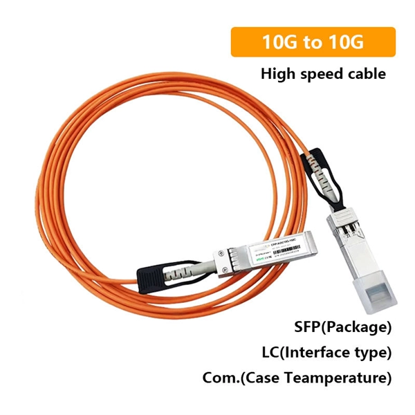
Below are eight SFP-based choices commonly used in tunnel monitoring, traffic analytics, and roadside IP cameras. Each item includes the key specs that matter in the field, a best-fit scenario with realistic numbers, and quick pros and cons. GigaVUE ® TA Series, part of the Gigamon Deep Observability Pipeline, aggregates traffic from SPAN/TAPs to deliver pervasive edge visibility. Supporting speeds from 1G to 400G, it improves monitoring efficiency and reduces costs through core intelligence and GigaVUE-OS. The GigaVUE TA Series is. An Aggregation or "Top-of-Rack" switch is designed to connect everything in a rack at high speeds, then have an even bigger pipe out to the rest of the network. The Pro Aggregation does this with it's SFP28 25Gbps ports. The regular Aggregation switch is best used to connect all devices in a rack. What Is an Aggregation Switch? An aggregation switch is a network device that consolidates traffic from multiple access switches, wireless access points, or other edge devices and forwards it to core switches or routers. By bundling multiple network connections into a single high-bandwidth link. We'll be happy to answer all of your technical, pricing & availibility questions. Road monitoring deployments live or die by link stability: vibration, temperature swings, moisture, and long fiber runs can turn a “works on the bench” SFP into a field failure.
[PDF]
In conventional network construction, we divide the switches into a hierarchical structure according to the number of connected network devices. Typically, we have three structural levels: access, aggregation, and core. An aggregation switch is a network device that consolidates traffic from multiple access switches, wireless access points, or other edge devices and forwards it to core switches or routers. By bundling multiple network connections into a single high-bandwidth link, aggregation switches help. Whether in enterprise networks, data centers, or campus environments, aggregation switches act as a bridge between access switches and core switches. It is essential for larger networks requiring efficient data flow. You may also. Due to all traffic in a system is transmitted to the core switch, it is required to have high reliability, high efficiency, manageability, and low latency. Generally, it adopts the managed switches in the core layer. The core layer is an integral part in networking, but it is not requested in all. Switch aggregation, also known as link aggregation or trunking, is a method used in computer networking to combine (aggregate) multiple network connections in parallel. This arrangement increases throughput beyond what a single relationship could sustain, offers redundancy in case one of the links.
[PDF]
Huawei MA5683T is an aggregation Optical Line Terminal (OLT), it supports up to 6 service slots and can support a maximum of 12,000 subscribers (GPON). MA5683T has GICF/X2CS Uplink Board available for selection, and two power slot redundancy for DC power input. Ethernet link aggregation increases link bandwidth by bundling multiple physical links to form a logical link. Link aggregation can work in manual mode or Link Aggregation Control Protocol (LACP) mode. In manual mode, you must manually create an Eth-Trunk and add member interfaces to the Eth-Trunk. As shown in Figure 1, SwitchA and SwitchB are connected to the networks of VLAN10 and VLAN20, respectively, via Ethernet links, and there is a large amount of data traffic between SwitchA and SwitchB. Link aggregation has the following advantages:. Original operating mode: Two S5700s were configured with Eth-Trunk1, and the ports of the three lines that need to be communicated were added to Eth-Trunk1. Set the port to access to allow the corresponding VLAN to pass; so that the two floors of the network can communicate normally In this way. And there are two link aggregation types. In LACP mode, there are active and backup links and backup links are used for redundancy. For this example, we. Link Aggregation is a technology defined in IEEE 802. It enhances bandwidth, provides fault tolerance, and allows load balancing between connected devices. Key benefits of link aggregation: Higher.
[PDF]

It connects to two independent power sources, enabling automatic switching to a secondary source during primary source failures. This seamless transition prevents disruptions to connected devices and enhances operational reliability. A dual power switching box is precisely the kind of gadget that guarantees a constant flow of electricity as it enables the user to shift the operational state between two different energy supplies. It can be found in homes, workplaces, factories, and anywhere else where sudden cuts of energy can. The ATS Dual Power Distribution Box plays a pivotal role in providing efficient low-voltage power solutions, ensuring that power flows seamlessly, even in the event of an outage. This comprehensive guide offers insights into the mechanisms and benefits of the ATS Dual Power Distribution Box. Transfer switches and sub panel boxes are key components in dual power switching cabinets. Transfer switches automatically switch between power sources during outages, ensuring uninterrupted power and system reliability. This redundancy ensures that if one power source fails, the other can immediately take over, minimizing downtime and preventing. A dual power switch helps you manage two power sources for one system. You can use it to keep your equipment working if the main power stops. This device quickly changes from the main supply to a backup source. This seamless transition.
[PDF]

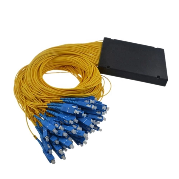
A typical fiber optic splice enclosure consists of several key components that work together to protect and organize the fiber splices. Standard enclosures contain: 1) Housing, 2) Cable fixation clamps, 3) Splice trays, 4) Sealing system. A splice box (also known as splice distributor) is a housing in which fiber optic cables begin or end. Fiber optics are fanned out in splice boxes that are situated at the end of fiber optic transmission paths. Optical cable joint box The optical cable joint box permanently connects two optical cables together and has a joint part for protecting components. The optical cable connection part, that is, the optical cable joint, is the part where the. An optical cable split fiber box, also known as a fiber distribution box or fiber optic splice closure, is a device used to terminate, splice, and distribute optical fibers. In this response, we will focus on the. This guide optimizes the original text by delving deeper into the three pillars of fiber network longevity: the impact of splicing technology, the strategic selection of splice boxes, and the essential maintenance protocols needed to ensure sustained, high-speed functionality. Fibre optic cables are manufactured in standardized lengths –.
[PDF]

In this article, I'm going to describe how to set up Link Aggregation between two managed switches to provide connectivity, redundancy, and expanded bandwidth. Managed switches provide many advantages for a growing network, including support for VLANs, QoS, and Trunking. I touched on simple VLAN configuration a while back. in the United States and in other countries. App Store and the Apple logo are trademarks of Apple Inc., registered in the U. Google Play and the Google Play. Link Aggregation in UniFi allows you to combine two or more ethernet ports into one. The NVR is connect via Fibre to the USW as well. So. ? Any hints welcome! Archived post. New comments cannot be posted and votes cannot be cast. Imagine transforming multiple network cables into one giant, super-speed "data highway. " That's exactly what link aggregation does. It combines multiple Ethernet connections into a single logical connection, boosting speed, enhancing. Thank you for purchasing the Ubiquiti Networks® EdgeSwitch® XG. This Quick Start Guide is designed to guide you through installation and also includes warranty terms. TERMS OF USE: All Ethernet cabling runs must use CAT6A (or above). It is the professional installer's responsibility to follow local.
[PDF]
They support link aggregation protocols such as Link Aggregation Control Protocol (LACP) and Static Link Aggregation, which allow multiple physical links to be combined into a single logical connection. This enhances bandwidth, redundancy, and ensures failover capability in case of a. The three layers of a traditional three-layer network design are the core layer, aggregation layer, and access layer. Together, these layers can offer consumers a network that is safe, reliable, and affordable. As the physical part of the aggregation layer, aggregation switches typically play a. An aggregate switch is a high-capacity network switch that consolidates connections from multiple access switches, acting as a central point for managing network traffic and providing enhanced bandwidth capabilities. It is essential for larger networks requiring efficient data flow. This article looks at what each such tool does, compares how they differ from each other, and offers suggestions as to what sort of network each. The aggregation (sometimes also called distribution) layer is a real crossroad. Its primary goal is to increase network scalability by providing a single place to interconnect multiple access switches and the core layer.
[PDF]
Backbone cable connects telecommunications spaces through dedicated infrastructure pathways, serving as the primary network connection between entrance facilities, equipment rooms, and telecommunications rooms. Structured cabling is an infrastructure that arranges the wires and cables of a building in an organized and modular way. In contrast to traditional point-to-point layouts, a structured cable setup clearly defines wiring standards. A structured cabling system is composed of six subsections, each. As data center environments scale in density and complexity, system integrators must make critical decisions about fiber architecture. Choosing between MPO and LC (Lucent Connector) fiber impacts compatibility, scalability, and deployment efficiency. Understanding how each solution fits within a. This Section defines the general design requirements for a uniform Intra and Inter-Building Communications Optical Fiber Backbone Cabling Infrastructure that shall be followed for all OFCC Technology construction projects. All equipment shall be UL listed. All equipment and Installation Practices. Fiber aggregation is a common technique used in fiber optic networks to improve the infrastructure and increase network capacity. So, what exactly are fiber aggregation points? They are the centralized hubs where multiple fiber optic cables intersect. My extensive experience shows that backbone cabling consists of fiber optic cables or.
[PDF]
This guide covers the essential tools and step-by-step procedures for low-loss fiber optic cable repair. Fiber optic cables are the backbone of modern networks, delivering fast and reliable data transmission. Accidental cuts, breaks, or other damage can disrupt your network and cause costly downtime. With the right tools and techniques, you can efficiently repair damaged fiber cables and restore. While a cut or damaged fiber optic cable can temporarily take your network down, it is possible to quickly fix the cable with the right tools. This wikiHow article will teach you how to splice a cut fiber optic cable back together with a fiber optic stripper and cutter and a fiber optic crimper. Cracks and breaks in a live fiber optic cable can happen for various reasons. Damage can also be caused by defects during manufacturing, but a primary cause is mishandling. Fiber optic cables are typically damaged in one of two ways: A premade fiber optic cable suffers connector damage when too much pull-force is applied during installation. This can occur on long cable runs through tight conduit or duct, and also if the cable becomes caught or snagged. However, most issues are caused by simple, fixable problems. By following a structured troubleshooting process, you can quickly identify and resolve the issue. Begin by identifying the damage, which can be done using an Optical Time Domain.
[PDF]