Standards IEC 30129 and AS 30129 Telecommunications Bonding Networks for Buildings and Other Structures and Standard TIA607-E Generic Telecommunications Bonding and Grounding (Earthing) for Customer Premises provide guidance on the design and installation of the indoor grounding . Standards IEC 30129 and AS 30129 Telecommunications Bonding Networks for Buildings and Other Structures and Standard TIA607-E Generic Telecommunications Bonding and Grounding (Earthing) for Customer Premises provide guidance on the design and installation of the indoor grounding . Below is a comprehensive guide for implementing effective bonding and grounding systems in data centers. The Mesh-BN is the backbone of the bonding system, designed to ensure a uniform electrical potential across the entire data center. The whole structure consists of a metal circuit, a protect bus, and a ground wire. Network hardware is connected to PDUs and constantly. ed grounding kits shall be UL Listed, CSA Certified and RoHS compliant. Grounding strip and connectors shall be tin-plated. Grounding strip shall comply with EIA niversal mounting hole spacing and mount to standard racks and cabinets. The offering is designed with products that installers can use to make BICSI and ANSI/TIA/EIA-607 compliant installations.
[PDF]

When designing a cable tray wiring system, the designer should evaluate the National Electrical Code's (NEC) Equipment Grounding Conductor (EGC) options that are applicable for the project. Use the cable tray as the EGC. The metal in cable trays may be used as the EGC as per the limitations. Cable tray grounding wire is the safety connection that links your electrical system's cable tray to the ground. This provides a safe path for any stray electrical currents to flow safely into the earth, avoiding damage to your equipment and reducing the risk of electric shocks. EGCs are a critical component in electrical infrastructure, ensuring safety and compliance by providing a low-impedance path to. that system to lose its UL Classification. If you take what UL states literally, ANY cut to tray (ladder or wi e) would cause a loss of UL Classification. For example, when a straight section of tray is cut to length and used in conjunction with a factory fitting — this installation would also.
[PDF]

In a metal box, a wire type equipment grounding conductor can be attached to the box with a ground screw or clip and terminated to the switch or receptacle in the box. Connecting the receptacle grounding terminal to the metal box ensures an effective ground-fault current path. The basic rule achieves this through an equipment grounding jumper; four exceptions. A main bonding jumper is required to bond the service disconnect enclosure to the service neutral conductor [250. Not all boxes are metal or provide. The main bonding jumper bonds the neutral conductor to the equipment grounding conductor, enabling proper operation of overcurrent protective devices. Neutral conductors must be properly sized based on the load and installation method, with specific requirements for conductors in parallel or. According to the National Electrical Code (NEC), this connection is made between the grounded conductor (typically the neutral) and the equipment grounding conductor (EGC) system at the service equipment. Proper location and sizing are not just best practices; they are essential for ensuring that. NEC Article 250 is dedicated entirely to grounding and bonding, outlining the specific conductors and connections required. Grounding Electrode Conductor (GEC): This is the wire that connects the grounding electrode (the rod) to the grounding bus bar in the main electrical panel.
[PDF]
OPGW cable joint box installation involves several key stages: selecting the appropriate location, preparing both the cable and the joint box, splicing fibers, and sealing the joint box properly. Adhering to these steps ensures optimal performance and longevity of the. This manual is formulated in accordance with IEEE 1138 - 2008 and IEEE 524 - 1992, etc. OPGW has dual functions of aerial ground wire and fiber communication. This guide provides a comprehensive overview of OPGW joint box installation, highlighting its importance and offering step-by-step instructions to master the process. The company is the world's best opgw joint box installation supplier. We are your one-stop shop for all needs. Our staff are. This document covers all the activities usually performed by PRYSMIAN for on-site installation of OPGW fibre optic cables, including transport, installation, accessory assembly, verification of optical transmission characteristics and final certification. AFL provides detailed installation instructions on proper techniques for installing OPGW cable. Please review the document (WI-0298 Rev 1) before proceeding with installation. Furthermore, it explains how these elements ensure both structural stability and long-term performance. These accessories provide mechanical strength and secure connections.
[PDF]
In this video we show you how to dismantle a concrete telecommunications tower with a crane truck. Every health and safety measures at work were strictly comp. PTTG has experienced crews available to help when owners determine they no longer need their tanks, towers, or other structures and require them to be dismantled and removed, including scrap disposal and site cleanup. On occasion, tanks or towers cease to function or become too old to maintain. This can include towers, batteries, internal equipment, hazardous material, and communication shelter removal. We handle each project with safety and sticking to a budget in mind. Cellular tower demolition jobs can be trickier than most jobs. Legalities of what third parties have access to the site can cause issues–issues we will take care of. Our experienced team handles all aspects of decommissioning, including: • Mount & Antenna Removal – Dismantling old equipment with precision. • Microwave Decommissioning – Safely uninstalling.
[PDF]

Towers are not rooted by only pouring concrete—they require extensive soil analysis, wind loads, types of towers, and seismic activity to determine the necessary foundation for safety and sustainable use. A communication tower foundation design is the structural blueprint that determines the anchor point of the tower on the ground. This article delves into the intricate process of civil construction tailored. Tower owners must comply with a multi-layered regulatory, engineering, and safety framework that governs tower siting, where a cell tower can be built, how it must be designed, and how it operates throughout its lifecycle. These requirements ensure public safety, structural integrity, regulatory. Here are six foundation types for communication towers that work for a wide range of situations and environments. If you're planning a new installation, knowing the basics of these foundations can help you establish a secure and durable tower that will be a community asset for years to come. Telecom (Telecommunications) towers are a generic description of radio masts and towers built primarily to hold telecommunications antennas. As such antennas often have a large area and must be precisely pointed out, such towers have to be designed and built to limit wind induced movement. The Contractor shall employ a quality control program that will ensure that engineering, fabrication.
[PDF]
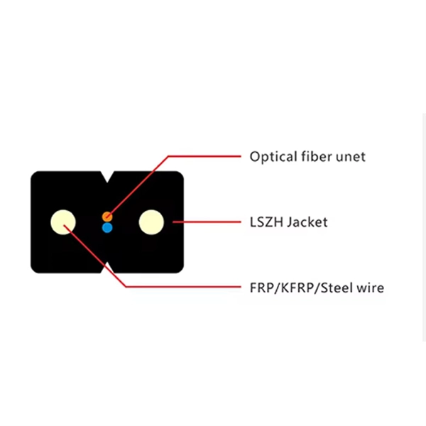
The FIBERLIGN EZ Cushion Suspension uses elastomer inserts to reduce static and dynamic stresses at the support point in the OPGW system. Structural reinforcing rods are not needed for installation; strain relief relies solely on the cushion inserts. ADSS Anchor Tension Clamps are hardware fittings used to securely terminate and anchor ADSS fiber optic cables on poles or towers without damaging the cable. ADSS Suspension Clamps are used to support ADSS fiber optic cables on poles by allowing safe hanging with controlled grip and minimal stress. technical specialist at Spring Optical, focusing on Data Center cabling Solution, FTTA Solution, FTTH Solution, and ODN Solution for global telecom, ISP, and data center network deployments. What Is a Cable Tension Clamp in Fiber Optic Networks? In aerial fiber optic networks, cable stability is. At Gcabling, we provide a complete set of reliable, corrosion-resistant tension clamp solutions designed to ensure safe and stable cable deployment in overhead networks. With a combination of stainless steel wire and reinforced nylon body, Fibeye tension clamps offer excellent durability and performance. Do you need a reliable, durable, and. In 2015, Jera line started to produce clamps and brackets for FTTX fiber optic cable deployment. Cable clamp and bracket are very important factor.
[PDF]
