
Cable Trays* — Max two 24 in. (610 mm) wide by max 6 in. (151 mm) deep open-ladder cable tray with channel-shaped side rails formed of 0. 54 mm) thick aluminum or min 0. In practice, cable tray dimensions are a system of interrelated measurements —width, depth, length, and material thickness—that directly affect cable fill compliance, heat dissipation, structural loading, and long-term expandability. From an engineering standpoint, cable tray dimensions are not. Perforated Cable Tray System expertly constructed from high-grade stainless steel, offering exceptional durability and resistance to corrosion. With side height 100mm. A properly designed and installed cable tray system will provide. Studs — Wall framing to consist of wood studs or channel shaped steel studs. Wood studs to consist of nom 2 by 4 in. Additional studs shall be used to completely frame. Best Size: Here, deep trays (75mm to 150mm) are used since power cables are typically thick and heavy. Data cables, such as your Wi-Fi or computer ones, are extremely sensitive. They do not get hot; however, they do not like to hang or sag. In case a data cable folds in an excessive manner, the. ect the minimum bend ra-dius for cables as they exit the bottom of the cable tray. A rung spacing of 6 to 9 inches (150 to 230 mm) is preferable when the cable tray cont d for instrumentation and control applications that require additional protec eferred to support and protect numerous small.
[PDF]

An Optical Splitter, also known as a beam splitter, is a passive optical device that divides a single input optical signal into two or more output signals. Conversely, it can also combine multiple signals into one. Knowing the difference between a splitter and an optical coupler helps you build better networks. You make your network work better when you pick the right device for each job. You can connect many users to one port with 1:n or 2:n splitters. By dividing a single optical signal from a central Optical Line Terminal (OLT) into multiple outputs for Optical Network Terminals (ONTs) at users' homes, splitters eliminate the need for dedicated fibers to each residence—slashing infrastructure costs while scaling network reach. This guide. In a Passive Optical Network (PON), a single optical fiber carries massive amounts of data using light. Signal Input: The fiber splitter receives the optical signal from the upstream network node and enters the splitter through the input fiber. Signal Distribution: Inside the splitter, according to the design structure and different. Splitters are passive optical devices that divide or combine optical signals, and they come in various types, including power splitters, uneven splitters, and wavelength-division multiplexing (WDM) splitters. Each type serves specific applications, enabling efficient use of optical infrastructure.
[PDF]

A ladder type cable tray tee is a fitting used to create a branch in a cable tray system, allowing cables to be routed in three directions. Its "T" shape provides a secure and efficient way to split cables from a main tray into two separate paths, ensuring organized and flexible. A cable tray tee and tee cover are components used in cable management systems to support and protect electrical and data cables. Here's a brief explanation of each:. Rigid steel cable tray tee fitting with zero tangent, safety bottom, and full accessory support. ventilation to heat producing cable such as power communication and other with the same or different width of the cable run. All fittings are available in sizes and types corresponding to the straight cable tray sections. These fitting are including: elbow, horizontal cross, vertical inside. NOTE : Equal or un equal tees can be supplied. When ordering state widths W1xW2xW3.. Office: 147/22 Nguyen Sy Sach Street, 15 Ward, Tân Binh Dist, HCMC,VN. Is it possible to connect 2 cabletrays with a "branch piece (left picture)" instead of a "tee (right picture)". The tee has 3 connectors, the branch piece only has 1 connector. I would like to ajust the "Type properties -> Fittings -> Tee" with the branch family, but can't get it accomplished.
[PDF]
For TDM-PON, a passive optical splitter is used in the optical distribution network. In the upstream direction, each ONU (optical network units) or ONT (optical network terminal) burst transmits for an assigned time-slot (multiplexed in the time domain). In this way, the OLT is receiving signals from only one ONU or ONT at any point in time. In the downstream direction, the OLT (usually) continuously transmits (or may burst transmit). ONUs or ONTs see their own data through the address labels embe.
[PDF]

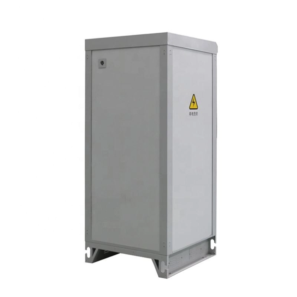
Whether you're an electrician or a DIY enthusiast, this tutorial will help you understand the fundamentals of wiring a distribution box for a residential setup. Hey, in this article we are going to see the Single Phase Distribution Box Wiring Diagram and Connection Procedure. A distribution board or distribution box is where the main power supply is distributed to multiple loads. And all the switching and protective devices are installed in the. The DB panel board controls the flow of electricity. It protects homes and industries from electrical hazards. It ensures that circuits are safe, organized, and easy to manage. A properly installed electrical distribution box is important for. Electrical systems power our homes, offices, and industrial facilities, but behind every reliable electrical setup lies a crucial component that often goes unnoticed: the distribution box. This essential piece of equipment serves as the nerve center of your electrical system, managing power flow. Welcome to our channel @Electricalgenius In this video, we'll take you through a detailed step-by-step guide on wiring a home distribution DB (Distribution Board) box. Distribution. Distribution box The system diagram usually shows the electrical connection and configuration inside the distribution box in a graphical way, including busbars, circuit breakers, fuses, load devices and other elements. In practical applications, the corresponding system diagram can be drawn.
[PDF]
Optical Modules Market Segments - by Product Type (Transceivers, Receivers, Transmitters, Amplifiers, and Others), Application (Data Centers, Telecommunication, Enterprise Networking, and Others), Distribution Channel (Online Stores, Direct Sales, Indirect Sales, and Others), Form. Optical Modules Market Segments - by Product Type (Transceivers, Receivers, Transmitters, Amplifiers, and Others), Application (Data Centers, Telecommunication, Enterprise Networking, and Others), Distribution Channel (Online Stores, Direct Sales, Indirect Sales, and Others), Form. Optical Module Chip Market size was valued at US$ 823 million in 2024 and is projected to reach US$ 1. 52 billion by 2032, at a CAGR of 8. The Optical Module Market grew from USD 26. 53 billion in 2025. Data centers will keep dominating optical module demand as AI and cloud drive revenue growth through 2030. Optical module demand is being pulled in two directions at once, faster bandwidth for dense networks and tighter constraints on power, security, and lead times. With global R&D projected to. The global Optical Modules market is projected to grow from US$ 17590 million in 2024 to US$ 56786 million by 2031, at a CAGR of 15. 8% (2025-2031), driven by critical product segments and diverse end‑use applications, while evolving U. tariff policies introduce trade‑cost volatility and.
[PDF]

This guide shows you how to organize circuit breaker wiring properly. You will learn to build a safe, efficient, and professional electrical system today. Circuit breaker wiring configurations involve organizing main switches, busbars, and branch breakers within a distribution box. Messy distribution boxes are dangerous and very hard to fix. You lower the chance of circuits getting too hot or overloaded when you pick the right box for your needs. When installing or troubleshooting a power distribution system, understanding how to correctly connect the main electrical supply to the control panel is crucial. Professional electrical panel schedule tool for creating detailed load distributions, calculating circuit loads, balancing phases, and ensuring NEC compliance for electrical distribution panels. Panel schedules are essential for electrical system documentation, load analysis, and NEC compliance. Material preparation: Prepare the required circuit breakers, wires, wiring ties and other materials, and ensure that they meet the design drawings and installation requirements. Location determination: Determine the installation position of the circuit breaker according to the position of the. Hey, in this article we are going to see the Single Phase Distribution Box Wiring Diagram and Connection Procedure. And all the switching and protective devices are installed in the.
[PDF]
