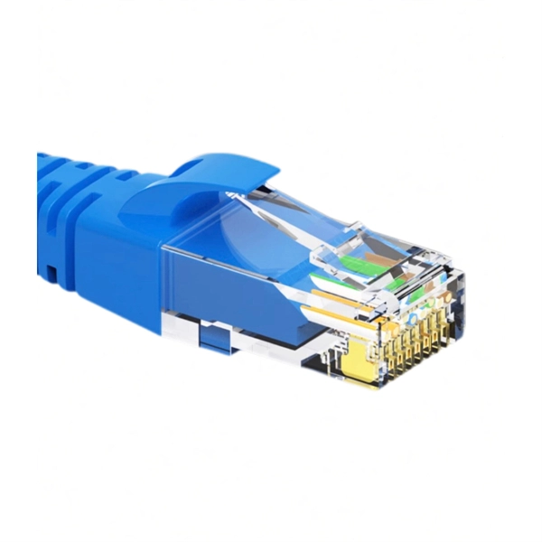
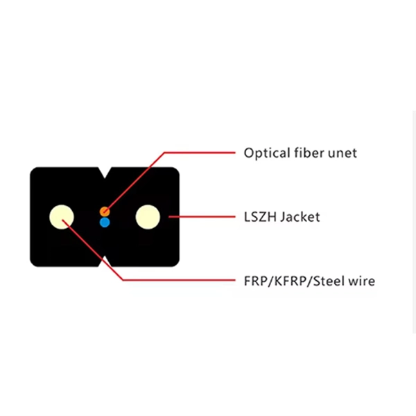
A8: Yes, multimode fiber optic cable can support high-speed data transmission depending on the fiber type and network equipment used. Multimode fiber (MMF) is an optical fiber designed to carry multiple light propagation paths—or modes—simultaneously. This is made possible by its relatively large core diameter, typically 50 or 62. 5 microns, compared to the ~9-micron core in single-mode fiber. The wider core accepts light from. Multi-mode optical fiber is a type of optical fiber mostly used for communication over short distances, such as within a building or on a campus. Multi-mode links can be used for data rates up to 800 Gbit/s. Multi-mode fiber has a fairly large core diameter that enables multiple light modes to be. In the realm of telecommunications and networking, multimode fiber optic cable plays a crucial role in efficiently transmitting data over short to medium distances. This guide aims to provide a concise understanding of multimode fiber optic cable and its applications. These fiber cables are structurally designed to transmit several light signals simultaneously, each of which is directed. Unlike copper cables, which rely on electrical signals, fiber optics use pulses of light to transmit data—offering unmatched bandwidth, low interference, and long-distance capabilities. But not all fiber cables are created equal: multimode (MM) and single mode (SM) fibers are the two primary types.
[PDF]
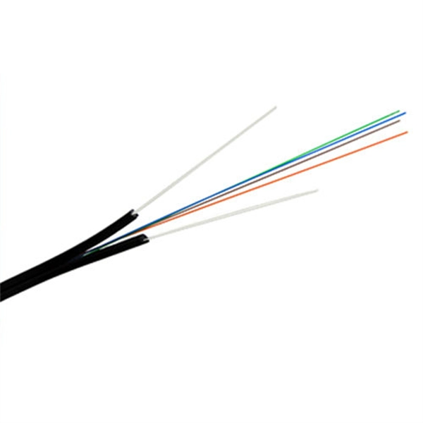
They are the bridge between fiber optic cables in the field and the equipment or patch panels that manage them. By combining factory-installed connectors with spliced bare fiber, pigtails ensure that network installers can create fast, reliable, and cost-effective terminations. Fiber pigtails are simple in appearance, yet essential in function. Get the wrong connector type, the wrong polish, or skip proper fusion splicing technique—and you're looking at elevated signal loss, increased back reflection, and a. In such contemporary fiber optic communication systems, low-loss, and connectivities, which have reliability, are crucial for not only maintaining high-speed but also high-quality data transmission. The most urgent stage of the process is, in fact, separating fiber optic pigtail, also known as. High performance optical pigtails are a defining factor in ensuring any network performs to the highest level. Prysmian ofers an extensive range of optical pigtails for use in FTTx, telecommunications, data communications and CATV applications. All pigtails are fully qualified to Telcordia GR326. A fiber optic pigtail is a type of fiber optic cable with only one end that has a factory-terminated connector and the other end exposed as bare fiber. Characterized by having an optical fiber connector on one end and a bare fiber end on the other, they are primarily used to connect optical transceivers or other optical.
[PDF]

Cable Trays* — Max two 24 in. (610 mm) wide by max 6 in. (151 mm) deep open-ladder cable tray with channel-shaped side rails formed of 0. 54 mm) thick aluminum or min 0. In practice, cable tray dimensions are a system of interrelated measurements —width, depth, length, and material thickness—that directly affect cable fill compliance, heat dissipation, structural loading, and long-term expandability. From an engineering standpoint, cable tray dimensions are not. Perforated Cable Tray System expertly constructed from high-grade stainless steel, offering exceptional durability and resistance to corrosion. With side height 100mm. A properly designed and installed cable tray system will provide. Studs — Wall framing to consist of wood studs or channel shaped steel studs. Wood studs to consist of nom 2 by 4 in. Additional studs shall be used to completely frame. Best Size: Here, deep trays (75mm to 150mm) are used since power cables are typically thick and heavy. Data cables, such as your Wi-Fi or computer ones, are extremely sensitive. They do not get hot; however, they do not like to hang or sag. In case a data cable folds in an excessive manner, the. ect the minimum bend ra-dius for cables as they exit the bottom of the cable tray. A rung spacing of 6 to 9 inches (150 to 230 mm) is preferable when the cable tray cont d for instrumentation and control applications that require additional protec eferred to support and protect numerous small.
[PDF]
Facility location affects data center interconnection more than you might expect. High-performance interconnects and access to quality networks are two of the most vital considerations when selecting a colocation provider. However, without a strategic location, these benefits. Data center interconnect (DCI) is private network connectivity between multiple data center facilities that lets you treat geographically separated infrastructure as a unified environment. Instead of routing traffic between sites over the public internet, DCI uses dedicated circuits that provide. Interconnection is an over-arching term that refers to many different physical and virtual connections companies can select to exchange data, provide business continuity and customer services, and address specific business objectives. Interconnection in colocation data centers are vital for fast. Following are some of the drawbacks or limitations of data centers. Limited Local Control: Companies outsourcing to data centers have less direct control over their infrastructure because the hardware and support staff are located remotely. Data center facilities can work together by sharing resources and passing workloads between one another. This interconnection is typically achieved through high-capacity interfaces, including dedicated private lines, dark fiber, Ethernet, and internet-based connections. With DCI, SPs can host critical.
[PDF]

In this guide, we take a deep dive into the design, performance, and applications of liquid cold plates, which are essential for thermal management in industries like data centers, telecommunications, aerospace, and defense. In this study, we conducted an experimental study on the heat sink performance at a constant volumetric airflow rate under various pressure conditions and verified the effect of the change in the density of the working gas on electronics cooling performance. First, we measured the flow rate of. Electronic circuits and systems designed for earth orbiting space applications and outer planetary exploration are required to operate reliably and efficiently under extreme temperature conditions. This requirement is dictated by the fact that the operational environments associated with some of. Cold plate cooling systems are revolutionizing how high-performance electronics manage heat in demanding environments. EMS providers deliver production-ready electronic systems for applications such as avionics, radar, communications, and unmanned platforms, with processes. For aerospace and space applications, where packaging and the optimal use of space, weight, and power are important, adequate and efficient cooling is a limiting factor due to the increased heat flux rates from compact-design electronic units. From a thermal energy management perspec-tive, immersion cooling is better than.
[PDF]

Solar energy offers data centers a path to reduce their carbon footprint and operational expenses. Major tech companies like Google and Apple are already leading the way, demonstrating that solar-powered data centers are environmentally responsible and economically viable. Data centers are the backbone of our digital world, powering everything from streaming services and cloud storage to remote work platforms and IoT devices. As our reliance on digital infrastructure grows, so does the energy consumption of these mission-critical facilities. Currently, data centers. Solar offers clean power at predictable costs, can be built fast at many scales, and pairs well with batteries to deliver reliability. In this article, we explain why data centers use so much energy, how solar powers data centers, how batteries and microgrids keep servers online, and why these. 2022 to 35 gigawatts (GW) in 2030. The United States accounts f d tap into suitable energy sources. Renewable energy is the answer, but it must be cost-efective, able to meet enormous demand without inte zed by explosive growth and demand. The emergence of AI, data streaming, cloud computing, and.
[PDF]

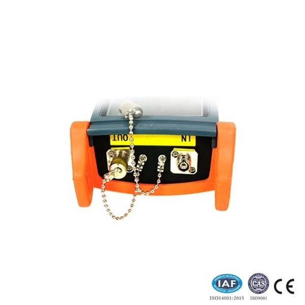
This report covers the optical, environmental, and mechanical performance of the LC-UPC, singlemode fiber optic BOAs, provided by Tyco Electronics, Fiber Optics Business Unit. Qualification testing was completed by a third party in July 2004. IDEAL FOR DEBUGGING OPTICAL POWER PERFORMANCE & OPTICAL INSTRUMENT CALIBRATION CORRECION & FIBER SIGNAL ATTENUATION. As optical passive devices, FS attenuators are mainly used in fiber optic to debug optical power performance & optical instrument calibration correction & fiber signal. L-com offers an extensive line of dual wavelength (1310/1550nm) Singlemode fiber optic attenuators. These versatile in-line attenuators are the perfect solution for attenuating Singlemode fiber connectors for both lab and commercial applications. Constructed of the highest quality materials and. zation system's perfo. the power of an optical signal. Our LC/APC single mode attenuators can handle a maximum o 1 watt of optical input power. This device contains one ale and one female LC/APC port. LC/APC optical attenuators can be ordered in attenuation. Fixed loopback type attenuators from OMC offer defined control of optical signals in both integrated and add-on products. Depending on the project or need, fixed attenuators can limit (attenuate) the amount of light passing through to the exact levels your project or application requirement.
[PDF]

Optical modules (also known as fiber optic transceivers) are essential components in modern communication networks, enabling high-speed data transmission by converting electrical signals into optical signals and vice versa. Among various optical module form factors, SFP (Small Form-Factor Pluggable). A fiber optic transceiver (also called an optical transceiver) is a compact module that both transmits and receives data signals through optical fibers. It serves a dual purpose — transmitting electrical signals as light pulses and receiving light pulses to convert them back into electrical form. An optical module usually consists of an optical transmitting device (TOSA, including a laser), an optical receiving device (ROSA, including a photodetector), functional circuits,main control circuit board (PCBA), housing and optical (electrical) interface and other components. How do optical. At the heart of fiber optic technology lies a crucial component: the optical transceiver. Let's explore the key aspects of optical transceivers to help you navigate.
[PDF]
Leaders will gather at the World Economic Forum Annual Meeting 2026 to discuss how to protect the environment while also driving economic growth. The next phase of global growth will be shaped by digital intelligence and the energy infrastructure that supports it. The Global Energy Interconnection (GEI) Journal publishes original research on theories and developments as well practical applications on principles of large scale low carbon energy generation, transmission, distribution & storage technologies, global energy interconnection & system developments. The provision of low carbon energy to our society is a key issue at the heart of sustainable development of global energy supply. China's concept of Global Energy Interconnection recognizes the importance of energy inter-connectivity for clean energy transition and repre-sents one of the boldest visions for low-carbon development at the national, regional strial Revolution in the 1870s.
[PDF]

A ladder type cable tray tee is a fitting used to create a branch in a cable tray system, allowing cables to be routed in three directions. Its "T" shape provides a secure and efficient way to split cables from a main tray into two separate paths, ensuring organized and flexible. A cable tray tee and tee cover are components used in cable management systems to support and protect electrical and data cables. Here's a brief explanation of each:. Rigid steel cable tray tee fitting with zero tangent, safety bottom, and full accessory support. ventilation to heat producing cable such as power communication and other with the same or different width of the cable run. All fittings are available in sizes and types corresponding to the straight cable tray sections. These fitting are including: elbow, horizontal cross, vertical inside. NOTE : Equal or un equal tees can be supplied. When ordering state widths W1xW2xW3.. Office: 147/22 Nguyen Sy Sach Street, 15 Ward, Tân Binh Dist, HCMC,VN. Is it possible to connect 2 cabletrays with a "branch piece (left picture)" instead of a "tee (right picture)". The tee has 3 connectors, the branch piece only has 1 connector. I would like to ajust the "Type properties -> Fittings -> Tee" with the branch family, but can't get it accomplished.
[PDF]
The data from September 2023 shows that 21 countries have achieved penetration rates higher than 50%. The UAE leads the ranking with 99,3%, while Singapore positions itself second at 97,1%. Hong Kong (95,3%), China (92,9%), and South Korea (91,5%) complete the top 5 positions. This report provides an analysis of Omdia's Fiber Development Index (FDI). The FDI quantifies and ranks the level of investment in fiber optical networks across nine metrics on a country-level basis. This analysis helps industry stakeholders, including policymakers, regulators, service providers. The Mobile Connectivity Index measures the performance of 173 countries against the key enablers of mobile internet adoption. In the European. Global Fiber-optic Cable key players include ZTT, YOFC, Prysmian, HTGD and FiberHome. Global top five manufacturers hold a share about 40%. Asia-Pacific is the largest market, with a share over 60%, followed by North America, with a share about 16 percent. 8 billion by 2029 from USD 3. 4% from 2024 to 2029. Rapid expansion of data centers, cloud services, and 5G infrastructure is driving strong adoption of fiber optic solutions. 80% during the forecast period (2023-2032). This expansion is driven by surging demand for high-bandwidth networks, 5G.
[PDF]
Check the electrical load and ensure that the sensors do not exceed the 10 Amp maximum. Check each wire for damage that may lead to a short. Replace any damaged cables. Check the tightness of electrical connections along the. In modern power systems, distribution boxes are the core equipment for power distribution and control, and their stable operation is crucial to ensuring the safety and reliability of power supply. However, in actual applications, distribution boxes often encounter a series of problems, which not. The Electrical Distribution Box is a very important part of the power system, improper installation will cause a lot of danger and loss. Here are some things that go wrong with an Electrical Distribution Box installation: Poor contact of the ground wire: The ground wire is the safety guarantee of. When it comes to electrical work, the small details inside a junction box can make a big difference in safety and performance. Even experienced DIYers sometimes make simple wiring mistakes that can lead to tripped breakers, poor connections, or potential fire hazards. It ensures smooth power flow, efficiently distributing electricity to various systems. However, like any other electrical device, a 3 Phase Electrical Distribution. They tell you if electricity is flowing through the wire. With your tester, check the flow of electricity at each wire before it enters the box. Using a light switch as a simple example, check each of the three wires.
[PDF]

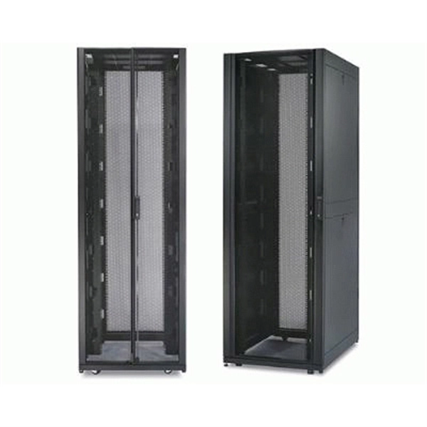
In this blog, we'll walk through the standard procedures for installing racks and assembling MPO systems in modern data centers. Before any hardware is installed, detailed planning is essential. Rack placement must consider airflow, power distribution, cable routing, and physical. Proper installation of components in a data center server rack is crucial for optimal performance, efficient maintenance, and long-term reliability of your IT infrastructure. The term breaks down into two distinct phases: “racking” involves assembling and mounting servers, switches, storage devices, and networking equipment into. Best Practices for Data Center Rack and Stack Installation in 2025. Data centers are the backbone of modern technology, and ensuring their infrastructure is installed correctly can significantly impact performance and scalability. Data. However, before you get down to installation itself, it's necessary to prepare for it. A preparatory stage includes several important pre-installation steps that ensure smooth and durable functioning. These include: Choosing the right rack type. Server furniture differs a lot. Modern manufacturers. Four-Post Racks To mount two-post racks, the equipment has to be bolted to two vertical posts, in most cases at the front. They are simple, cheaper than other types, and occupy less space. They are a good choice for small IT rooms or closets with minimal depth requirements and lightweight devices.
[PDF]
Standards IEC 30129 and AS 30129 Telecommunications Bonding Networks for Buildings and Other Structures and Standard TIA607-E Generic Telecommunications Bonding and Grounding (Earthing) for Customer Premises provide guidance on the design and installation of the indoor grounding . Standards IEC 30129 and AS 30129 Telecommunications Bonding Networks for Buildings and Other Structures and Standard TIA607-E Generic Telecommunications Bonding and Grounding (Earthing) for Customer Premises provide guidance on the design and installation of the indoor grounding . Below is a comprehensive guide for implementing effective bonding and grounding systems in data centers. The Mesh-BN is the backbone of the bonding system, designed to ensure a uniform electrical potential across the entire data center. The whole structure consists of a metal circuit, a protect bus, and a ground wire. Network hardware is connected to PDUs and constantly. ed grounding kits shall be UL Listed, CSA Certified and RoHS compliant. Grounding strip and connectors shall be tin-plated. Grounding strip shall comply with EIA niversal mounting hole spacing and mount to standard racks and cabinets. The offering is designed with products that installers can use to make BICSI and ANSI/TIA/EIA-607 compliant installations.
[PDF]
The primary application of fiber Bragg gratings is in optical communications systems. They are specifically used as. They are also used in optical and with an, or (OADM). Figure 5 shows 4 channels, depicted as 4 colours, impinging onto a FBG via an optical circulator. The FBG is set to reflect one of the channels, here channel 4. The signal is reflected back to the circulator where it is directed down and dropped ou.
[PDF]