
An Optical Splitter, also known as a beam splitter, is a passive optical device that divides a single input optical signal into two or more output signals. Conversely, it can also combine multiple signals into one. Knowing the difference between a splitter and an optical coupler helps you build better networks. You make your network work better when you pick the right device for each job. You can connect many users to one port with 1:n or 2:n splitters. By dividing a single optical signal from a central Optical Line Terminal (OLT) into multiple outputs for Optical Network Terminals (ONTs) at users' homes, splitters eliminate the need for dedicated fibers to each residence—slashing infrastructure costs while scaling network reach. This guide. In a Passive Optical Network (PON), a single optical fiber carries massive amounts of data using light. Signal Input: The fiber splitter receives the optical signal from the upstream network node and enters the splitter through the input fiber. Signal Distribution: Inside the splitter, according to the design structure and different. Splitters are passive optical devices that divide or combine optical signals, and they come in various types, including power splitters, uneven splitters, and wavelength-division multiplexing (WDM) splitters. Each type serves specific applications, enabling efficient use of optical infrastructure.
[PDF]

Cable Trays* — Max two 24 in. (610 mm) wide by max 6 in. (151 mm) deep open-ladder cable tray with channel-shaped side rails formed of 0. 54 mm) thick aluminum or min 0. In practice, cable tray dimensions are a system of interrelated measurements —width, depth, length, and material thickness—that directly affect cable fill compliance, heat dissipation, structural loading, and long-term expandability. From an engineering standpoint, cable tray dimensions are not. Perforated Cable Tray System expertly constructed from high-grade stainless steel, offering exceptional durability and resistance to corrosion. With side height 100mm. A properly designed and installed cable tray system will provide. Studs — Wall framing to consist of wood studs or channel shaped steel studs. Wood studs to consist of nom 2 by 4 in. Additional studs shall be used to completely frame. Best Size: Here, deep trays (75mm to 150mm) are used since power cables are typically thick and heavy. Data cables, such as your Wi-Fi or computer ones, are extremely sensitive. They do not get hot; however, they do not like to hang or sag. In case a data cable folds in an excessive manner, the. ect the minimum bend ra-dius for cables as they exit the bottom of the cable tray. A rung spacing of 6 to 9 inches (150 to 230 mm) is preferable when the cable tray cont d for instrumentation and control applications that require additional protec eferred to support and protect numerous small.
[PDF]
This article will deeply explore the unique charm of optical circulators from five aspects: the forefront of technological innovation, efficient cyclic transmission, wide application fields, excellent and stable performance, and future development prospects. Frontier of. An Optical Circulator is a non-reciprocal device that routes light from one port to the next, in a unidirectional manner. This unique device has broad applications in many fields, from optical telecommunications to fiber-optic sensor systems. They are crucial components in modern optics and photonics, enabling the efficient routing of optical signals. The basic principle of an optical. The evolution of optical circulators can be traced back to the advancements in fiber optics technology during the late 20th century, which necessitated the development of devices capable of managing complex light pathways. They are technically related to Faraday isolators, and on a broader scale similar to electronic circulators.
[PDF]

Key finding: This paper develops analytical models and design procedures of ultra-wideband Wilkinson power dividers using linearly tapered transmission lines (TTLs) which provide size reduction and broadband performance. Read more. Power dividers are the passive electronic equipment used for splitting the power. They are now being employed in a variety of communications applications such as telephonic, antennas configurations, mobile connectivity, internet technology, & optics, etc. They come up with very low loss, operate at. RF and microwave power splitters and dividers create two copies of the same signal, while ideally preventing crosstalk between the outputs. Doing this with minimal loss while maintaining signal integrity is a challenge. In this article we explain how power splitters work and what the tradeoffs are. The rise of wireless connectivity requirements for applications such as Internet of Things (IoT), cellular, and automotive electronics is resulting in systems that are increasingly using RF signals, components, and subsystems. Often, designers need to direct these signals to more than a single. A power divider is a passive electronic device used in radio frequency (RF) and microwave applications to split an input signal into multiple output signals with equal or specified power levels, while maintaining impedance matching to minimize signal reflection and loss. How can power dividers.
[PDF]

This article provides a detailed technical comparison between fiber optic and copper cables, offering a clear perspective for engineers, network architects, and procurement managers. The core distinction between the two technologies lies in the physics of data. There are significant differences in performance between ADSS cables (all-dielectric self-supporting optical cables) and traditional optical cables, which are mainly reflected in the following aspects: 1. This type of fiber optic cable is designed to support its own weight without the need for additional support structures like messenger wires. The ADSS. There are several factors to assess when deciding which cable type is right for your application, including speed of connection for new customers, ease of changes and repairs, installer certification requirements, and the ability to expand the network over time. ADSS Fiber Optic Cables are a type of optical fiber cable designed specifically for. All-dielectric self-supporting (ADSS) cable is a type of optical fiber cable that is strong enough to support itself between structures without using conductive metal elements. It is used by electrical utility companies as a communications medium, installed along existing overhead transmission.
[PDF]
At the heart of every optical transceiver lie three essential components, often called the “Three Pillars” of optical communication: Laser — generates light. Modulator — encodes data onto the light. Photodiode — decodes light signals back into electrical form. An optical receiver is a device that converts light signals traveling through fiber optic cable back into electrical signals that electronic equipment can process. The core function of the optical receiver relies on a physical phenomenon known as photoelectric conversion. When a modulated light signal. The polarization independent isolator is made of three parts, an input birefringent wedge (with its ordinary polarization direction vertical and its extraordinary polarization direction horizontal), a Faraday rotator, and an output birefringent wedge (with its ordinary polarization direction at. Our optical receivers and detectors make photodetection easy and provide the lowest noise and cleanest response possible. Our broad offering spans wavelength ranges from UV to short-wave IR for free-space and fiber-coupled configurations in many versions: high-speed, general-purpose, balanced. Optical receivers are devices that convert light signals into electrical signals using photodetectors, which come in various types such as photodiodes and avalanche photodiodes. The document covers key concepts such as the operating principles of these detectors, noise types, signal-to-noise ratio.
[PDF]
Typically, an optical circulator consists of three main parts: wave plates, Faraday rotators, and birefringent crystals. When light enters the circulator, it is split into two beams with orthogonal polarization states. An optical circulator is a non-reciprocal device that directs light signals sequentially between multiple ports. You can think of it as a traffic controller for light, ensuring signals flow in one direction without interference. Unlike optical isolators that block reflected light, a circulator routes optical signals in a specific order — typically Port 1 → Port 2 and Port 2 →. An optical circulator is a three- or four-port optical device designed such that light entering any port exits from the next. This means that if light enters port 1 it is emitted from port 2, but if some of the emitted light is reflected back to the circulator, it does not come out of port 1 but. Optical Circulators are crucial components in modern optical communication systems, enabling the efficient routing of optical signals between different ports. In this comprehensive guide, we will explore the definition, basic principles, and importance of Optical Circulators, as well as their. The optical circulator is a fundamental device, acting as an advanced traffic controller that provides strict directional control over light signals within the network architecture.
[PDF]

NPO (Near-Packaged Optics) is a transitional technology bridging traditional pluggable modules and CPO. It integrates the optical engine and GPU chip side-by-side on the same high-performance PCB or organic substrate, connected via ultra-short high-speed circuits. Its core concept is to remove digital processing units such as DSPs and CDRs from the module, constructing a purely analog "linear direct-drive" optical link. In the LPO architecture: The transmitter uses a high-linearity driver chip to directly drive the optical modulator, converting the. Near-packaged optics (NPO) helps send data faster. It puts the optical engine close to the switching chip. This makes things work better. NPO lets you upgrade easily. You do not have to redesign your whole system. It lowers energy costs. Among the emerging technologies, LPO (Linear Pluggable Optics), NPO (Near-Packaged Optics), and CPO (Co-Packaged Optics) represent three important stages in the evolution of next-generation data center optical networking. Understanding how these architectures differ is essential for designing. Traditional optical modules typically rely on DSPs (Digital Signal Processors) to handle signal equalization, retiming, and compensation, mitigating attenuation and distortion during transmission. They are not concepts at the same level, but rather.
[PDF]

However, there are still some scenarios where an optical drive is necessary or desirable. What is an Optical Drive?. THe Optical memory is an electronic storage medium that uses a laser beam to store and retrieve digital (binary) data. In optical storage technology, a laser beam encodes digital data on an optical disc or laser disc in the form of tiny pits arranged in a spiral pattern on the surface of the disc. In this article, we'll explore the pros and cons of having an optical drive and help you decide whether you need one. Although a number of optical formats have been used over time, the most common examples are optical discs such as the compact disc (CD) and the digital versatile disc (DVD). The primary components of an optical drive include a laser, a lens system, a motor for spinning the disc, and a decoder to interpret the data. It is commonly found in computers, laptops, and gaming consoles. Optical drives are essential for installing software, playing movies, and backing up data.
[PDF]

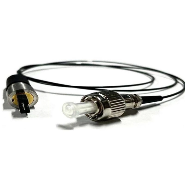
The optical module is usually composed of Transmitter Optical Subassembly (TOSA, containing a laser LD Chip), Receiver Optical Subassembly (ROSA, containing a photodetector PD Chip), a driving circuit, and an optical and electrical interface. Its schematic is shown in. This section explains the structure of a typical pigtail butterfly module, which gets its name from the two rows of seven leads at right angles on each side of the metal package plus an optical fiber pigtail at one end (Fig. Let's look at the internal structure (Fig. 2) of a common butterfly. Optical modules are devices used to connect network devices, transmit and receive data between network devices, and can be used to convert optical and electrical signals. The optical module is a very important component in an optical communication system. Optical devices are the core components of optical modules. TOSA and ROSA in Common Optical Transceiver Modules For ordinary optical transceiver modules, there are two optical devices, TOSA and ROSA, which have opposite effects.
[PDF]

With protective doors, dust-proof 2). Suitable for many types of modules, used in cabling work area subsystem 3). Embedded type surface, easy for installation and removal 4). Available for fiber optic SC simplex or LC duplex and can be used in both surface mounted. 1). This termination box supports 0. 0mm pigtails and 2x3mm indoor drop cables. Discover the Welink FTB-1005: a high-quality 1 Core Fiber Optic Outlet for FTTH. RoHS certified, compact, durable, and easy to install. Compact Design: Space-saving footprint (86x86mm) ideal for residential and office wall mounting. Splice Protection: Integrated tray securely holds fusion. FTTH Terminal box is a compact fiber terminal for use at the final fiber termination point in the customer premises. It provides mechanical protection and managed fiber control in an attractive format suitable for use inside customer premises, A variety of possible fiber termination techniques are. 1 Core Fiber Optic Desk Terminal Box for SC, FC Adapter, Patch Cord or Pigtail Description: 1). It provides a secure and convenient location for fiber optic splicing, connecting the drop cable and the passive optical equipment of the optical network. protection and management for the FTTx network building. Features: Scope of application 3. Specification: Applications: 1 Core Fiber Optic Terminal Box is used as a termination point for the feeder cable to connect with drop cable in FTTx communication network.
[PDF]

The wavelength of the 40G QSFP+ SR4 optical module is 4x850nm, while the 40G QSFP+ LR4 optical module adopts CWDM coarse wavelength division multiplexing technology, with four wavelengths of 1271nm, 1291nm, 1311nm, and 1331nm. The fiber type and connector are different. 40GBASE-ER4 is a long-reach 40GbE optical standard that delivers 40Gbps transmission over single-mode fiber up to 40km using QSFP+ transceiver. It achieves this reach by multiplexing four CWDM optical lanes into a duplex LC fiber interface, allowing long-distance connectivity without requiring. While 100G and 400G technologies continue to advance, 40G QSFP+ optical modules remain a mainstream, cost-effective solution for upgrading small to medium-sized data centers. It is commonly deployed in data centers, enterprise backbone networks, and metropolitan area networks where stable, high-speed transmission over extended distances is. In the deployment of 40G networks, the 40G QSFP+ optical module is one of the most widely used, defined by IEEE 802. The two basic interface specifications for QSFP+ optical modules are 40G BASE-SR4 and 40G BASE-LR4. In this blog, ETU-LINK will talk about. The QSFP+ module is designed for use in 40GBASE Ethernet throughput up to 10km, 30km or 40km over single mode fiber (SMF) using a wavelength of 1310nm via duplex LC connectors. This transceiver is compliant with QSFP+ MSA and IEEE 802. Digital diagnostics functions are also available.
[PDF]

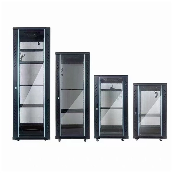
Here's a step-by-step guide to help you set up your fiber distribution box seamlessly: Before installing the fiber distribution box, ensure that your optical cables are properly prepared for connection. The optical fiber distribution box allows people to easily access the optical fibers in the box, and can well protect the optical fibers. In addition, the drawer structure also facilitates high-density wiring and good cable management. However, because optical fibers are fragile and can be easily. Keeping this page as a placeholder for now. Have any questions? Talk with us directly using LiveChat. Fix the rack to the ground with expansion bolts. Top installation: Dimensions of four connection holes on the top according to the. This instruction describes the installation of the Fiber Distribution Frame (FDF) manufactured by Corning Optical Communications. To order accessories that are purchased separately, contact Corning Optical Communications customer care for assistance. Read and understand this procedure (as well as. Optical fiber distribution frame is the wiring connection equipment between optical cable and optical communication equipment or between optical communication equipment. Distribution boxes are especially essential for FTTH networks, where they enable the efficient connection and management of optical fibers from a central.
[PDF]

FS optical line protection switch features 1+1 backup and less than 15 ms fast switch to the standby fiber link that ensures business uninterrupted when malfunction occurs. An optical protection switch is a critical component in fiber optic communication systems designed to safeguard optical signals and infrastructure from damage due to power surges, signal overloads, or system failures. These switches ensure signal integrity, minimize downtime, and enhance network. 1+1 Optical Line Protection System for Fiber Protection, Bi-directional Protection in Dual Fiber, LC/UPC, Pluggable Module OLP (Optical Line Protection) is a device used in pairs, one at each end of the optical signal to protect network transmission line. OLP products include fiber optical line protection switches, optical bypass switches, optical cross connection, multi-channel. The FOSW-1x1 or 1x2 optical switch is based on opto-mechanical technology with proven reliability. OSW-W1x2 optical switch is a high performance electro-optical device, with low insertion loss (typic. In optical communication network, OLP monitors optical power of optical fiber and standby.
[PDF]

Built with GF's advanced silicon photonics technology, the SCALE CPO solution utilizes both coarse and dense wavelength-division multiplexing (CWDM, DWDM) for bi-directional data transmission over each optical fiber for significant improvements in bandwidth density and system. Built with GF's advanced silicon photonics technology, the SCALE CPO solution utilizes both coarse and dense wavelength-division multiplexing (CWDM, DWDM) for bi-directional data transmission over each optical fiber for significant improvements in bandwidth density and system. MALTA, N., May 04, 2026 (GLOBE NEWSWIRE) -- GlobalFoundries (Nasdaq: GFS) (GF) today announced the introduction of its SCALE™ optical module solution for co-packaged optics (CPO). GF's SCALE solution, or Silicon photonics Co-packaged Advanced Light Engine solution, is the industry's first Optical. MALTA, N. 9, 2024: IBM (NYSE: IBM) has unveiled breakthrough research in optics. These pressures are driving renewed momentum behind co-packaged optics (CPO). According to LightCounting, sales of lasers and photonic integrated circuits for optical transceivers are expected to grow from $2. 9B by 2029, fueled largely by AI data centers.
[PDF]
