
Cable Trays* — Max two 24 in. (610 mm) wide by max 6 in. (151 mm) deep open-ladder cable tray with channel-shaped side rails formed of 0. 54 mm) thick aluminum or min 0. In practice, cable tray dimensions are a system of interrelated measurements —width, depth, length, and material thickness—that directly affect cable fill compliance, heat dissipation, structural loading, and long-term expandability. From an engineering standpoint, cable tray dimensions are not. Perforated Cable Tray System expertly constructed from high-grade stainless steel, offering exceptional durability and resistance to corrosion. With side height 100mm. A properly designed and installed cable tray system will provide. Studs — Wall framing to consist of wood studs or channel shaped steel studs. Wood studs to consist of nom 2 by 4 in. Additional studs shall be used to completely frame. Best Size: Here, deep trays (75mm to 150mm) are used since power cables are typically thick and heavy. Data cables, such as your Wi-Fi or computer ones, are extremely sensitive. They do not get hot; however, they do not like to hang or sag. In case a data cable folds in an excessive manner, the. ect the minimum bend ra-dius for cables as they exit the bottom of the cable tray. A rung spacing of 6 to 9 inches (150 to 230 mm) is preferable when the cable tray cont d for instrumentation and control applications that require additional protec eferred to support and protect numerous small.
[PDF]

Work From Home Relay Protection Engineers often face challenges related to coordinating with on-site teams, accessing physical equipment remotely, and ensuring clear communication during installations and troubleshooting. In this comprehensive article, we delve into the best practices, challenges, and innovative solutions in relay testing and commissioning, placing a strong emphasis on. Relay protection is the discipline of designing schemes that detect faults, coordinate relays, and isolate equipment without outages. It emphasizes selectivity, coordination, fault response, and system behavior rather than individual relay devices. Relay protection is often misunderstood as a. What are the top challenges that a Protective Relay Technician might face in the first 90 days? What does a day in the life of a Protective Relay Technician look like? What are some tips for helping a Protective Relay Technician fit into the company culture? What are some career development tips. fer more functions than ever. Substation Protection and Control (P&C) systems based on the IEC 61850 standard and energy sources from inverter-based renewable of engineers and technicians. In complex power networks, coordination between protective devices becomes essential to ensure selective operation and minimize disruptions. However, achieving coordination.
[PDF]
Follow these steps to configure DHCP server or relay on a switch. The VLAN for which DHCP server will be configured on switch is assigned to the ports connecting to the DHCP clients. You can do this by applying a relevant port profile to the port. Hi all, Have a Unifi USW Pro that I want to use as my core switch. Running into a DHCP relay issue where I have a windows server with 2 DHCP scopes, one for default vlan traffic one for BYOD devices. I want the switch to do the routing so that if an SSID is tagged a vlan X, the switch with ip. I'm trying to obtain a DHCP IP for the client directly connected to the Branch Office Core switch. I can ping the DHCP Server IP from the branch office core switch. For more information about port profiles, see. A DHCP relay forwards DHCP packets between the DHCP server and clients. When the DHCP server and clients belong to different network segment, the DHCP relay needs to be configured. The DHCP. Hello All, Attached guide provides in-depth understanding about DHCP Server and DHCP Relay Implementation. Hi Priyank, thank you for the complete information. I have DHCP configured on a linux server and the core switch which has layer 3. -Vlans are created and access ports are configured with the respective vlans on the access switches. -used network command -used default-router command which.
[PDF]

Numerical relay are embedded with specialized digital signal processor (DSP) as the computational hardware. By using DSP as the relay's processor, the relay is capable of meeting the fundamental protective requirements such as reliability, sensitivity, selectivity and speed . Thus, various protective devices are used to protect the power system, of which digital signal processor (DSP) numerical relays are capable of significantly improve protection operations. Therefore. Manuals and User Guides for Samwha DSP DSP-VIP-PM Motor Protection. We have 1 Samwha DSP DSP-VIP-PM Motor Protection manual available for free PDF download: Manual Samwha dsp DSP-VIP-PM Motor Protection Pdf User Manuals. View online or download Samwha dsp DSP-VIP-PM Motor Protection Manual. Many of the new protection relays are microprocessor based and are generally referred to as numerical relays. This means that signals from transducers are sampled at fixed time intervals, digitally encoded, and processed by equipment which resembles a computer to derive relaying information, e.
[PDF]
The global protective relay market size was worth more than USD 2. 82 billion in 2025 and is poised to witness a CAGR of over 5. 5%, crossing USD 4. 82 billion revenue by 2035, fueled by rising integration of digitalization & IoT in protective relay. The global market for Protection Relays was valued at US$ million in the year 2024 and is projected to reach a revised size of US$ million by 2031, growing at a CAGR of %during the forecast period. A protection relay is a smart device that receives inputs, compares them to set points, and provides. The Protective Relay Market was valued at USD 3. 9% through 2024 to 2030, reaching nearly USD 3. 4%, according to Strategic Market Research. Protective relays are essential components of modern power systems. The Protection Relays Market encompasses the design, manufacturing, and deployment of electromechanical, solid-state, and digital relays that monitor electrical systems for faults or abnormal conditions and initiate protective actions.
[PDF]
This paper analyzes the basic principle and function of relay protection, summarizes the common fault types, and analyzes the fault analysis methods and treatment measures combined with actual cases. A method of fault tracking for relay protection devices is presented in this paper. Fault tracking means that after the failure of relay protection devices, the anomalies and warning informa-tion are obtained through data-mining technology, and then, the fault tracking algorithm is used. Relay fault diagnosis refers to the process of identifying and analyzing faults or abnormalities in protective relays. However, in actual operation, the relay protection device may cause failure due to hardware failure, software problems or external. For a long time, the fault diagnosis technology of relay protection consists of isolated cases and does not have a systematic method.
[PDF]

This article describes the anti-pumping relay, its definition, function, and circuit diagram. In a circuit breaker it is desired that when close and trip operation is performed on the circuit breaker with the closing coil energized, the subsequent closing operation should be prevented. So let's. Anti-Pumping relay is nothing but a NO contact, which means when the circuit breaker in closed condition the relay will be as NO point and if the circuit breaker in open condition the relay will be as NC Condition. The anti-pumping relays is connected in series with the circuit. An anti pumping relay (also called antipumping relay or Y-relay and ANSI 94 Trip or Trip-Free Relay) is a protective device that prevents a circuit breaker from closing repeatedly when a continuous close command is present. In simple terms, it stops your circuit breaker from “pumping” – which means. Anti-pumping relays are used in circuit breakers to prevent the breaker from closing unexpectedly after tripping. If the TNC switch fails (Trip normal close) or there is any problem with the CB (circuit breakers) closing circuit, the continuous CB (circuit breakers) close command can be extended to. Why is the Anti-Pumping Relay Used? A circuit breaker is a very important equipment for a high-voltage power system. It protects the system from high current or voltage during a faulty condition.
[PDF]

This certification requires completion of the following two courses, which may be completed in any order within an 18-month period: National Electrical Code 2020, 4 days, 2. 8 CEUs, which you can take In-Person or Virtual, Live. Electrical Safety for Inspectors, 4 days, 2. After completion of all requirements you must submit your certification application. Your certification package will include a certificate and laminated wallet card. {{$pageCtrl. description}}. General requirements for certification include passing an exam or exams, specific industry related experience, successful performance of key role specific activities, and personal recommendations (Levels III and IV). Once earned, certification must be maintained through Continuing Professional. Whether you specialize in fire protection systems, building and life safety, or electrical, our acclaimed certification programs can help verify your competence and set you apart from your peers. Empowering employees to work safely and effectively with Megger's offering of courses and certification programs in electrical maintenance, electrical safety, as well as through our custom-tailored training. Copyright © 2026 Megger, all rights reserved. Participants gain practical experience with real-world equipment, learning to interpret.
[PDF]

A new updated course will be released for sale during the spring of 2026. SFS 6002 Electrical safety -course is mandatory in Finland for all persons involved in electrical works: installers, managers, assistants etc. The course is valid for 5 years and shall be renewed to maintain the. Electrical qualification 1 (Electrical Safety Act 1435/2016 Section 66) The holder of electrical qualification 1 may work as an electrical work supervisor and supervisor of operations in all electrical and operational work. These regulations lay down binding requirements, which cover e. A person who builds, repairs or maintains electrical installations, or repairs and maintains electrical appliances must be professionally qualified, and Tukes must be notified before any such operations begin. The operators are called electrical or lift contractors. A company or a natural person. Electrical safety is not just a legal requirement – it's part of everyday workplace safety. Cad Sä Oy has developed the Electricity Passport, a new training model in which SFS 6002 training is carefully tailored to the specific electrical tasks each participant will perform in their project. The. Finnish electrical safety card (Sähkötyöturvallisuuskortti SFS 6002) is intended for people working in the maintenance and servicing of electrical installations, machines and equipment up to 1000 V in Finland.
[PDF]

87N high-impedance protection requires special class × current transformer cores with equal transformation ratios. The 7SJ60 relay can alternatively be connected in series with the 7UT613 relay to save this CT core. Earth faults on the secondary side are detected by current relay 51N. However, it has to be time-graded against downstream feeder protection relays. Primary circuit-breaker and relay may be replaced by fuses. Go back to contents ↑. Relay 7UT612provides numerical ratio and vector group adaptation. Matching transformers as used with traditional relays are therefore no longer applicable. Line CTs are to be connected to separate stabilizing inputs of the differential relay 87T in order to ensure stability in the event of line through-fault currents. Relay 7UT613provides numerical ratio and vector group adaptation. Go back to contents ↑. The directional functions 67 and 67N do not apply for cases where the transformers are equipped with the transformer differential relays 87T. Go back to contents ↑.
[PDF]

Generator protection relays are devices that detect abnormal operating conditions and isolate the generator from the system to prevent damage. These relays act as the first line of defense and are installed with strict adherence to IEC Standard for Protection Relays. Protecting generators from different electrical, mechanical, and thermal stresses is known as generator protection. To safeguard machines from overloads and unusual circumstances, preventive measures are required. Faults are inevitable even with effective design, construction, and operation. Below is an overview of the different types of relays used in generator systems, their functions, and their specific applications. Electromagnetic relays use. Generator Protections are broadly classified into three types: Class A, B and C. Class A covers all electrical protections for faults within the generating unit in which generator field breaker, generator breaker and turbine should be tripped. What Are Generator Protection Relays? Generator protection. There are various protection relays and those are used for protection against a wide variety of conditions. The fundamental principles that are covered in this course are equally applicable to. IEEE C37. 2 defines the IEEE “numerical” function designation for all protective relay functions. This presentation primarily uses the designations from the Beckwith M-3425A relay, which in most cases follows IEEE C37.
[PDF]
🏃♂️�� Grenada Intercol 2023 – Boys Open 4x400m Relay Watch the thrilling relay action from the 2023 Republic Bank Inter‑Secondary Schools Athletic Championships (INTERCOL) held at the Kirani James Athletics Stadium in St. more 🏃♂️🔥 Grenada Intercol 2023 – Boys Open 4x400m Relay. Our Relay Services provides the full range of services such as: TTY, Voice Carry Over (VCO), two-line Voice Carry Over (2LVCO), Hearing Carry Over (HCO), Speech-to-Speech (STS), Visually Assisted Speech-to-Speech (VA STS), ASCII, Voice, Enhanced Voice Carryover (Captioned Telephone or CapTel), and. No description has been added to this video. Audio tracks for some languages were automatically generated. Learn more Enjoy the videos and music you love, upload original content, and share it all with friends, family, and the world on YouTube. CARIFTA GAMES GRENADA 2026 | GIRLS 4x400M RELAY U17 FINAL | DAY 3 Until This Happened 😱 No description has been added to this video.
[PDF]

This handbook covers the code of practice in protection circuitry including standard lead and device numbers, mode of connections at terminal strips, colour codes in multicore cables, dos and donts in execution. Also principles of various protective relays and schemes including special protection. Read this document and the documents listed in the additional resources section about installation, configuration, and operation of this equipment before you install, configure, operate, or maintain this product. Users are required to familiarize themselves with installation and wiring instructions. presentation of protection and control relaying. The report will identify methodology behind these practices, present issues raised by the integration of microprocessor relays and the internal logic and external communication configurations, ying. The objective of this presentation is to convey a basic understanding of protective relays to an audience of engineers already familiar with low voltage protective device coordination. HT panel protection relay. The HT power supply is received from GO switch and distributed to the. The handbook for protection engineers includes guidelines on protective circuitry, protective relay principles, and testing procedures for switchgear and relays. It covers standard codes, wiring practices, and norms for protecting generators, transformers, and lines, and provides detailed.
[PDF]
Key techniques include using bonding agents, saw-cutting, re-pouring concrete, mechanical connectors, and epoxy injection. Conventional methods like epoxy grout injection can address cracks effectively. Learn how to prep and bond a next-day concrete pour to repair a cold joint. This guide walks through practical surface prep, bonding methods, and timing so you can create a strong, durable joint. You'll gain actionable, plain-language steps and tips you can apply on real job sites. Identify cold. A cold joint is a common imperfection in concrete construction, occurring when fresh concrete is poured next to a section that has already begun the setting process. This discontinuity prevents the two pours from chemically integrating into a single monolithic unit, creating a weak plane within the. A cold joint in concrete is an area or surface with a structural discontinuity caused by the delayed concrete pouring between two layers of concrete. This issue compromises the structural integrity and durability of the concrete. This transition from a plastic or fluid state to a semi-solid state creates a discontinuity.
[PDF]
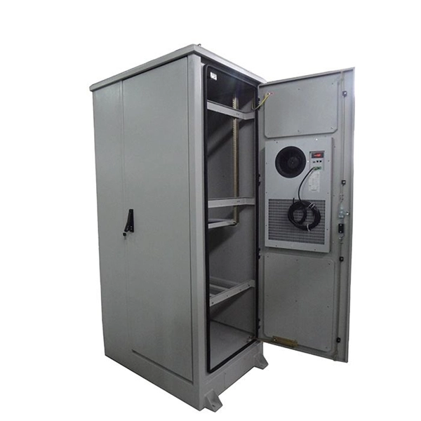
Its primary purpose is to ensure safe and efficient power distribution while providing protection via fuses or circuit breakers against overloads and short circuits. Distribution boxes are built with durable materials, typically metal or high-grade plastic, designed to endure. Most distribution boxes contain circuit breakers or fuses that function as protective barriers for the connected wiring and electrical devices. These safety components monitor the electrical flow continuously. When electrical problems occur—such as short circuits or excessive power draw—the circuit. Its primary role is to ensure safety, control, and organization. Let's break down its core functions. Centralized Control and Distribution The main function of a Distribution Box is to act as a central hub. The single, thick cable bringing power from the utility company enters this box. Inside. A low voltage distribution box safely manages and protects electrical circuits, ensuring reliable power distribution and enhanced safety in any building. It is commonly used in homes, offices, and industrial settings to control and protect electrical circuits. It helps organize, protect, and control electrical connections in residential, commercial, and industrial electrical systems.
[PDF]


