
Cable Trays* — Max two 24 in. (610 mm) wide by max 6 in. (151 mm) deep open-ladder cable tray with channel-shaped side rails formed of 0. 54 mm) thick aluminum or min 0. In practice, cable tray dimensions are a system of interrelated measurements —width, depth, length, and material thickness—that directly affect cable fill compliance, heat dissipation, structural loading, and long-term expandability. From an engineering standpoint, cable tray dimensions are not. Perforated Cable Tray System expertly constructed from high-grade stainless steel, offering exceptional durability and resistance to corrosion. With side height 100mm. A properly designed and installed cable tray system will provide. Studs — Wall framing to consist of wood studs or channel shaped steel studs. Wood studs to consist of nom 2 by 4 in. Additional studs shall be used to completely frame. Best Size: Here, deep trays (75mm to 150mm) are used since power cables are typically thick and heavy. Data cables, such as your Wi-Fi or computer ones, are extremely sensitive. They do not get hot; however, they do not like to hang or sag. In case a data cable folds in an excessive manner, the. ect the minimum bend ra-dius for cables as they exit the bottom of the cable tray. A rung spacing of 6 to 9 inches (150 to 230 mm) is preferable when the cable tray cont d for instrumentation and control applications that require additional protec eferred to support and protect numerous small.
[PDF]

An Optical Splitter, also known as a beam splitter, is a passive optical device that divides a single input optical signal into two or more output signals. Conversely, it can also combine multiple signals into one. Knowing the difference between a splitter and an optical coupler helps you build better networks. You make your network work better when you pick the right device for each job. You can connect many users to one port with 1:n or 2:n splitters. By dividing a single optical signal from a central Optical Line Terminal (OLT) into multiple outputs for Optical Network Terminals (ONTs) at users' homes, splitters eliminate the need for dedicated fibers to each residence—slashing infrastructure costs while scaling network reach. This guide. In a Passive Optical Network (PON), a single optical fiber carries massive amounts of data using light. Signal Input: The fiber splitter receives the optical signal from the upstream network node and enters the splitter through the input fiber. Signal Distribution: Inside the splitter, according to the design structure and different. Splitters are passive optical devices that divide or combine optical signals, and they come in various types, including power splitters, uneven splitters, and wavelength-division multiplexing (WDM) splitters. Each type serves specific applications, enabling efficient use of optical infrastructure.
[PDF]

A ladder type cable tray tee is a fitting used to create a branch in a cable tray system, allowing cables to be routed in three directions. Its "T" shape provides a secure and efficient way to split cables from a main tray into two separate paths, ensuring organized and flexible. A cable tray tee and tee cover are components used in cable management systems to support and protect electrical and data cables. Here's a brief explanation of each:. Rigid steel cable tray tee fitting with zero tangent, safety bottom, and full accessory support. ventilation to heat producing cable such as power communication and other with the same or different width of the cable run. All fittings are available in sizes and types corresponding to the straight cable tray sections. These fitting are including: elbow, horizontal cross, vertical inside. NOTE : Equal or un equal tees can be supplied. When ordering state widths W1xW2xW3.. Office: 147/22 Nguyen Sy Sach Street, 15 Ward, Tân Binh Dist, HCMC,VN. Is it possible to connect 2 cabletrays with a "branch piece (left picture)" instead of a "tee (right picture)". The tee has 3 connectors, the branch piece only has 1 connector. I would like to ajust the "Type properties -> Fittings -> Tee" with the branch family, but can't get it accomplished.
[PDF]
A fiber-optic splitter, also known as a, is based on a of an integrated waveguide power distribution device, similar to a The system uses an optical signal coupled to the branch distribution. The splitter is one of the most important in the link. It is an optical fiber tandem device with many input and output terminals, especially applicable to a passive optical network (,,,.
[PDF]
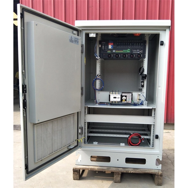
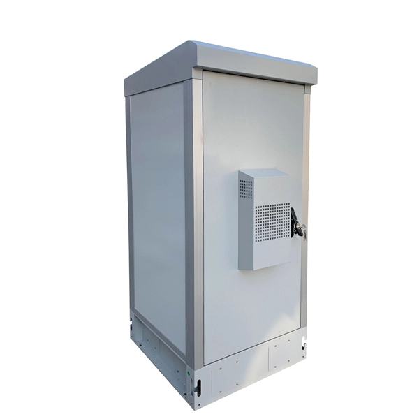
A fiber optic termination box is an enclosure designed to terminate incoming optical fiber cables and distribute optical signals to drop cables or patch cords. It integrates fiber splicing, adapter management, and cable protection in one compact unit. It is widely deployed in FTTH, FTTB, and other access networks to ensure stable signal transmission from backbone cables to end. ■ What is a Fiber Access Terminal (FAT)? A Fiber Access Terminal (FAT), also known as a Fiber Access Terminal Box (ATB) or Fiber Distribution Terminal (FDT), is a key component found in optimized fiber optic access networks for FTTH implementations. It acts like the "central nervous system". Fiber termination boxes play a vital role in ensuring efficient and reliable fiber management in FTTH applications. By understanding the components, types, and differences between various fiber management devices, businesses can make informed decisions when deploying and maintaining their fiber. But what exactly is the purpose of a fiber optic terminal box, and why is it so crucial in the realm of optical communication? First and foremost, a fiber optic terminal box serves as a robust protective shield for fiber optic cables and their delicate connections. It offers higher reliability and more flexible deployment and configuration than traditional terminal boxes. It is usually installed on the wall in the user's room or on the rack in the telecom room, and.
[PDF]
Segmented dimming is a feature of the Magic Leap 2 that applies a darkening tint behind specific digital content. Similar to a drop-shadow, this dimming improves the visual quality of a digital object by making it appear brighter or more opaque. The dimmer uses a lower resolution panel and therefore, developers must be conscious of it's use and is best used for larger objects. As of the February 2023 release, all virtual. The main scene of this project displays two cubes, one cyan and one red. The Segmented Dimmer material opacity will adjust based on the MLCamera stream value calculations. Think of this as a tint applied to the background under all the virtual content, in which you can control its opacity value. A Segmented Dimmer, which allows applications to locally. Th is function is commonly referred to as dimming control. Th is article describes some basic LED theory and several techniques used to provide dimming control to switched-mode LED drivers. Th e concept of the brightness of visible light from an LED is fairly easy to understand. Assigning a. It the utility model is related to LED light source room lighting field, more particularly to a kind of segmented LED dimming control circuit, a kind of segmented LED dimming control circuit, the light-source brightness of LED lamp is automatically adjusted to realize by the collective effect of.
[PDF]

Numerical relay are embedded with specialized digital signal processor (DSP) as the computational hardware. By using DSP as the relay's processor, the relay is capable of meeting the fundamental protective requirements such as reliability, sensitivity, selectivity and speed . Thus, various protective devices are used to protect the power system, of which digital signal processor (DSP) numerical relays are capable of significantly improve protection operations. Therefore. Manuals and User Guides for Samwha DSP DSP-VIP-PM Motor Protection. We have 1 Samwha DSP DSP-VIP-PM Motor Protection manual available for free PDF download: Manual Samwha dsp DSP-VIP-PM Motor Protection Pdf User Manuals. View online or download Samwha dsp DSP-VIP-PM Motor Protection Manual. Many of the new protection relays are microprocessor based and are generally referred to as numerical relays. This means that signals from transducers are sampled at fixed time intervals, digitally encoded, and processed by equipment which resembles a computer to derive relaying information, e.
[PDF]
Essentially, an OXC is a device that allows for the interconnection of multiple optical fibers, facilitating the routing of optical signals from any input fiber to any output fiber. This functionality is crucial for managing the vast amounts of data transmitted through optical. An optical cross-connect (OXC) is a network device that switches high‐speed optical signals between fiber inputs and outputs without converting them to electronics. In the 1980s, when transmission speeds supported by optical fibers increased from 45 Mbit/s to 2. 5 Gbit/s, carrier networks. The Optical Transport Network has emerged as a dominant standard to address these needs, offering robust transmission, multiplexing, switching, and management capabilities for optical signals. Compared with traditional ROADM based on separate boards and inter-board fiber patch cords, OXC uses integrated interconnections to build an all-optical switching resource pool, achieving highly integrated, fiber. Optical Cross-Connects (OXCs) are critical components in modern optical networks, enabling the switching of optical signals between different paths without the need for electrical conversion. This technology supports scalability, flexibility, and high performance for backbone networks, data‑center interconnects, and next-generation mobile.
[PDF]
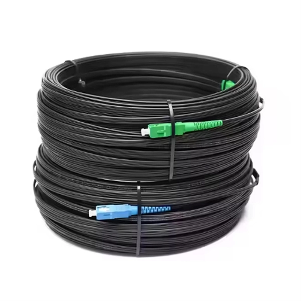
The reels are designed for handling fiber cables in temporary installations. It can be stacked, has room on the inside for storing connectors (size up to Probeam Sr. Fiber-optic cables on cable drums are versatile. For any kind of events, e. Trade fairs, sports events, conferences, filmed productions, etc. Fiber optic cables. Fiber optic cable reels are essential tools in the telecommunications and cable installation industries, designed to facilitate the handling, storage, and transportation of fiber optic cables. These reels are specially engineered to meet the precise needs of fiber optic cables, ensuring their. OCC is pleased to introduce the Modular Advanced Reel System (MARS), the industry's first lightweight cable deployment reel system designed specifically for the demanding needs of harsh-environment fiber optic installations. The drums have brakes, fold-in swivel handles, and drums of the. Mobile Cable Reel,Optical Cable Reel, Optical Fiber Take up Reel, Sturdy and Durable Stand, Easy to Grip Handles, Portable Signal Line Reel Black This product has sustainability features recognized by trusted certifications. Made with chemicals safer for human health and the environment.
[PDF]

The primary function of a fiber adapter panel is to provide a housing for fiber optic adapters or connectors. These adapters act as the interface between the terminated fiber ends and the active equipment, such as switches, routers, or servers. A fiber patch panel is a mounted enclosure—either rack-mounted or wall-mounted—used to terminate, manage, and interconnect multiple fiber optic cables. It acts as a hub for organizing splices and patch cords, streamlining fiber management and preserving signal integrity. This guide will focus on elucidating the aspects of the fiber patch panel, its accessories, the work done with such a device, and how to. Fiber optic networks are the backbone of fast, reliable internet and modern communications, but even the best fiber cables need the right connectors and patch panels to work efficiently. Connectors are the points where fiber cables link to devices, equipment, or other cables, and using the right. The fiber optic patch panel, also known as the fiber distribution panel, serves as the crucial component of the management of fiber optic cables. Also, the advantage of fiber optic patch panels is to reduce the loss of fiber optic transmission and facilitate engineers to troubleshoot. Serving as the network's centralized junction, it provides secure ports for both incoming and outgoing fibers, streamlining connection.
[PDF]

Generator protection relays are devices that detect abnormal operating conditions and isolate the generator from the system to prevent damage. These relays act as the first line of defense and are installed with strict adherence to IEC Standard for Protection Relays. Protecting generators from different electrical, mechanical, and thermal stresses is known as generator protection. To safeguard machines from overloads and unusual circumstances, preventive measures are required. Faults are inevitable even with effective design, construction, and operation. Below is an overview of the different types of relays used in generator systems, their functions, and their specific applications. Electromagnetic relays use. Generator Protections are broadly classified into three types: Class A, B and C. Class A covers all electrical protections for faults within the generating unit in which generator field breaker, generator breaker and turbine should be tripped. What Are Generator Protection Relays? Generator protection. There are various protection relays and those are used for protection against a wide variety of conditions. The fundamental principles that are covered in this course are equally applicable to. IEEE C37. 2 defines the IEEE “numerical” function designation for all protective relay functions. This presentation primarily uses the designations from the Beckwith M-3425A relay, which in most cases follows IEEE C37.
[PDF]

Multimode Fiber Optic Receivers are devices designed to interpret information contained in optical signals transmitted through multimode fibers. These receivers convert the optical signals into electrical signals, allowing the data to be processed and utilized by electronic systems. Multimode Fiber. They convert electrical signals into optical signals for transmission over fiber-optic cables and reverse the process at the receiving end. Now, the term 'multimode' stems from the fact that these transceivers use multimode fiber (MMF) cables, which can carry multiple beams of light — or 'modes' —. Multi-mode optical fiber is a type of optical fiber mostly used for communication over short distances, such as within a building or on a campus. Multi-mode links can be used for data rates up to 800 Gbit/s. Most systems operate by transmitting in one direction on one fiber and in the reverse direction on another fiber for full duplex operation. For applications where long-haul transmission is unnecessary, multimode SFP modules offer a practical. They have a wider core (around 50 to 62. 5 micrometers), which enables multiple modes or light paths to coexist within the fiber, thus resulting in modal dispersion at shorter distances but reducing its efficacy over longer stretches. The choice between Single-Mode Fiber (SMF) and Multimode Fiber.
[PDF]

A PLC Splitter takes one optical signal and splits it into many outputs. This helps share signals in fiber optic networks. Pick the split ratio that matches what you need. Lower ratios work for fewer users. Choose the connector type like SC . PLC optical splitters (planar waveguide optical splitter) is a key component in optical fiber communication networks and is widely used in optical fiber distribution systems such as FTTH (fiber to the home) and PON (passive optical network). A fiber optic PLC splitter distributes a single optical signal into multiple outputs with high uniformity and low loss, making it ideal for. PLC splitter, also called Planar Waveguide Circuit splitter, is a device used to divide one or two light beams into multiple light beams uniformly or combine multiple light beams to one or two light beams. It is a passive optical device with many input and output terminals, especially applicable to. What Is a PLC Fiber Splitter? A PLC (Planar Lightwave Circuit) splitter is a passive optical device that evenly distributes optical signals into multiple output ports using silica waveguide technology. Choose the connector type like SC, LC, or FC. This. That's where PLC splitters come in. These compact passive components help service providers and network engineers distribute a single optical signal across multiple outputs without the need for power or complex configurations. If you're building or upgrading a fiber network and wondering what a PLC.
[PDF]
An optocoupler is a coupling device used to couple optical signals. It's primarily employed to combine and split signals in optical networks, and it's also referred to as a directional coupler. Image alt: Optocoupler-Optical coupler The figure above depicts a 2x2 coupler with two input ports and. It is widely used for coupling or splitting light waves through waveguides or fibers and can be availed in the form of either active or passive devices. The main difference between active and passive couplers is that the passive coupler redistributes the optical signal without converting optical. Optical couplers, essential components in the realm of fiber optics and telecommunications, stand at the forefront of enabling efficient, versatile, and reliable optical signal processing. In ophthalmic imaging; the coupler: A-Z > O > What Is an Optical Coupler? Share Provide a valuable. A coupler is an optical device that combines or splits optical signals. The basic principle of a coupler is to transfer optical power from one or more input ports to one or more output ports.
[PDF]
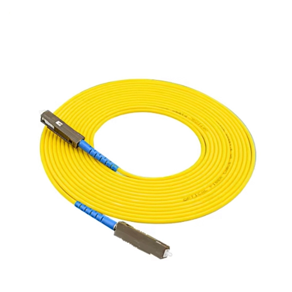
A fiber optic pigtail is a short length of optical fiber —typically 0. 5m to 2m—that has a factory-terminated connector on one end and bare fiber on the other end. The connector end is polished and tested under factory conditions, ensuring low insertion loss and high return loss. They are the bridge between fiber optic cables in the field and the equipment or patch panels that manage them. By combining factory-installed connectors with spliced bare fiber, pigtails ensure that network installers can create. The most urgent stage of the process is, in fact, separating fiber optic pigtail, also known as pigtail fiber or pigtail fiber optic cable. These short, pre-terminated cables play a vital role in terminating and splicing optical fibers, especially in complex fiber infrastructure such as data. Executive Summary: A fiber optic pigtail is one of the most commonly specified yet least understood components in structured cabling. Get the wrong connector type, the wrong polish, or skip proper fusion splicing technique—and you're looking at elevated signal loss, increased back reflection, and a. A fiber pigtail is a short optical fiber cable with a connector pre-installed on one end and a bare fiber on the other. The quality and.
[PDF]
