
Fusion splicing is the process of fusing or welding two fibers together usually by an electric arc. Fusion splicing is the most widely used method of splicing as it provides for the lowest loss and least reflectance, as well as providing the strongest and most reliable joint between. This guide reveals the secrets to fusion splicing with little fluff—just proven, straightforward techniques refined from years of work in the field. The goal is to fuse the two fibers together in such a way that light passing through the fibers is not scattered or reflected back by the splice, and so that the splice and the region surrounding it are almost as strong as the. A fusion splicer is a specialized tool used in fiber optic networks to join two fiber optic cables together permanently. This process creates a strong and reliable connection that can withstand. Splicing fiber optic cable is an extremely important phase for making dependable, high-speed communication infrastructures. Fusion splicing stands out as a superior technique for joining optical fibers, offering a seamless, low-loss connection that is crucial for reliable fiber optic networks. Let's explore the fundamentals of mechanical and fusion.
[PDF]

This practical file details experiments conducted in Optical Fiber Communication, covering modulation techniques, system components, and performance analysis. An optical fiber is a glass or plastic fiber designed to guide light along its length, widely used in fiber-optic communication, which permits transmission over longer distances and at higher data rates than other forms of communications. Fiber-optic communication is a method of transmitting. Availability of plastic optical fiber (POF) The plastic optical fiber used in some of these experiments is available for science distributors. It is a 1000micron (1mm) POF available from several suppliers. FOA has samples available at no cost for teachers at schools in the US. Key experiments include amplitude modulation, frequency modulation, and pulse width modulation, aimed at understanding fiber optic systems. This document summarizes 10 experiments on optical fiber communication: 1. Studying a 650mm fiber optic analog link and the relationship between input and received signals. Optical fiber communication Laboratory Optical fiber communication Laboratory List of Experiments: 1. To set up a analog optical fiber link 2. To measure the characteristics of LED and LASER 5. Tech curriculum designed to provide a comprehensive understanding of optical fiber communication systems. This lab offers an immersive, web-based simulator that enables you to explore and experiment with key concepts in optical.
[PDF]

Our list for Fiber optic products suppliers in Ecuador is one of the most comprehensive in the industry. As of May, 2026, we have compiled data on 23 verified listings. **** ZC Mayoristas Matriz. ****. As per the Volza's Ecuador Optical Fibers Exporters & Suppliers directory, there are 13 active Optical Fibers Exporters in Ecuador exporting to 37 Buyers. These facts are updated till 04-Jul-2025, and are based on Volza's Ecuador Exporters & Suppliers directory of Optical Fibers, sourced from 90+. We have local factory, delivery in any time and any place you want The most advanced technology and globle R&D team support A full set of test equipment that meets international standards Different cable design according to customer's needs LatamFiberHome was established in 2013. It's the first. Fabricante Cables Telecomunicaciones Opticable S. is an enterprise based in Ecuador. It operates in the Fiber Optic Cable Manufacturing industry. It was established on August 23, 2014. It currently has a total number of 1 (2024) employees. Contact Details: Purchase. Teldor is a well-established manufacturing company supplying cables to various industries around the world. As an industry-leading manufacturer of specialist cables, Teldor is a frontrunner in technical innovation. We provide an extensive range of cables designed to serve critical sectors such as.
[PDF]

Manta HM (stands for "high magnification") is an automated microscope for inspection of single and multi-fiber patch cords, bulkhead and transceivers, including but not limited to: MT, MPO, SN-MT, MMC, LC, FC, SC, CS®, SN®, MDC, E2000™, MXC, PRIZM, QSFP, ARINC . Manta HM (stands for "high magnification") is an automated microscope for inspection of single and multi-fiber patch cords, bulkhead and transceivers, including but not limited to: MT, MPO, SN-MT, MMC, LC, FC, SC, CS®, SN®, MDC, E2000™, MXC, PRIZM, QSFP, ARINC . Image shown is a representation only. Exact specifications should be obtained from the product data sheet. Order today, ships today. F3-SDLCLC-HM – Cable Fiber Optic LC/UPC Duplex To LC/UPC Duplex 9/125 1. 64' (500mm) from CompuCablePlusUSA. Pricing and Availability on millions of electronic. Buy now, ships today. that performs on-site drawing of copper. When drawing copper, PCA starts with 13 AWG solid copper conductor on custom built deploying devices, called Stems. The copper is pulled into drawing. CESS, 3 HOLE OT P NG S, 3 HO.
[PDF]

Receiver sensitivity is the lowest optical power level at which an optical receiver can successfully decode data with acceptable bit error rates (BER). It's a core parameter in optical transceiver specifications, indicating the module's capability to detect weak incoming signals. The standards body governing the application sets this specified BER. For example, SONET specifies that the BER must be 10 -10 or better. What Is BER? The bit error rate (BER) measures the data transmission precision within. Receiver sensitivity stands as a critical parameter impacting an optical transceiver's functionality. It denotes a module's capability to function in challenging environments and aids network operators in determining the system's maximum reach or link margin. Lower receiver. Among a group of optical receivers, a receiver is said to be more sensitive if it achieves the same performance with less optical power incident on it. The performance criterion for digital receivers is governed by the bit-error rate (BER), defined as the probability of incorrect identification of.
[PDF]

To use a power meter for fiber optic testing, always clean connectors first with lint-free wipes or click-to-clean tools. Select the correct wavelength and set your reference. You measure optical power in dBm or insertion loss in dB. Consistent procedures ensure accuracy. Verify light travels from. The most basic fiber optic measurement is optical power from the end of a fiber. This measurement is the basis for loss measurements as well as the power from a source or presented at a receiver. Typically both transmitters and receivers have receptacles for fiber optic connectors, so measuring the. An optical power meter measures the strength of light traveling through a fiber optic cable, giving you a reading in dBm (decibels relative to one milliwatt). This article will guide you through the methods, instruments, and key considerations for measuring fiber. Fiber optic cabling is the high-performance core of today's datacom networks. As network speeds and bandwidth demands increase, fiber performance requirements have become more stringent. Fiber testing is more important than ever. An OPM uses a photodiode to generate an electrical current proportional to optical power.
[PDF]
In fiber optic circuit technology an optical fiber link is used for transferring digital or analogue data in the form light frequency through a cable which has a highly reflective central core. Internally, the optical fiber.
[PDF]

Here's a step-by-step guide to help you set up your fiber distribution box seamlessly: Before installing the fiber distribution box, ensure that your optical cables are properly prepared for connection. The optical fiber distribution box allows people to easily access the optical fibers in the box, and can well protect the optical fibers. In addition, the drawer structure also facilitates high-density wiring and good cable management. However, because optical fibers are fragile and can be easily. Keeping this page as a placeholder for now. Have any questions? Talk with us directly using LiveChat. Fix the rack to the ground with expansion bolts. Top installation: Dimensions of four connection holes on the top according to the. This instruction describes the installation of the Fiber Distribution Frame (FDF) manufactured by Corning Optical Communications. To order accessories that are purchased separately, contact Corning Optical Communications customer care for assistance. Read and understand this procedure (as well as. Optical fiber distribution frame is the wiring connection equipment between optical cable and optical communication equipment or between optical communication equipment. Distribution boxes are especially essential for FTTH networks, where they enable the efficient connection and management of optical fibers from a central.
[PDF]
This updated list ranks the 20 largest fiber-optic cable companies worldwide and summarizes what each vendor is best known for—core product lines, regional strengths, and typical project fit. Use it as a fast shortlist when planning new FTTH/FTTA or data-center builds. Based on 2025 rankings from industry sources like Owire and TSCables, the top manufacturers are evaluated on market share, innovation, and global reach. We note certifications. Top 10 Fiber Optic Cable Manufacturers in 2025: Who to Choose & Why? Here's an updated list of the best fiber optic cable manufacturers, with FS and PHILISUN among the leaders driving innovation and connectivity worldwide. Selecting the right fiber optic company is the first critical step in. With the global fiber optic cable market valued at $13. 92 billion and growing at 10. 46% annually, choosing from the best fiber optic manufacturers ensures your business infrastructure meets current demands and future scalability requirements. 80% during the forecast period (2023-2032). This expansion is driven by surging demand for high-bandwidth networks, 5G.
[PDF]

Mechanical splicing is a fast way to join two fiber optic cables. Instead, you line up the fibers inside a small holder made of plastic or metal. The holder keeps the fibers steady. A special gel helps light move through the joint. In this guide, we'll walk you through exactly how to splice fiber without a fusion splicer, covering the tools you need, the step-by-step process, performance specs, and common mistakes to avoid. By the end, you'll be equipped to make clean, low-loss connections in any field scenario. Experts who add quality contributions will have a chance to be featured. Learn more Mechanical splicing is a. Executive Summary: A fiber optic pigtail is one of the most commonly specified yet least understood components in structured cabling. Get the wrong connector type, the wrong polish, or skip proper fusion splicing technique—and you're looking at elevated signal loss, increased back reflection, and a. Fiber optic cable splicing connects two cables, creating a strong link for fast data transmission. Fusion splicing uses heat to join fibers, while mechanical splicing aligns fibers without the need. This video will show you how to repair a damaged fiber optic cable strand without a fusion splicer. This temporary fix will get your network back up and running, giving you time to source new fiber cable. Fusion Splicing Fusion.
[PDF]

Fiber optic cables offer superior performance compared to copper cables, especially over long distances. They provide higher data transmission rates, larger bandwidths and are immune to electromagnetic interference. Fiber optic cables and copper wires are the two primary types of cables used in networks. Fiber optic cables transmit data using light waves, enabling higher. Fiber optic tends to be the more premium solution, while copper wiring is far more common, but why is that? What are the differences between these two cable types, and why might you want to pick one over the other? Here's everything you need to know about fiber vs. Copper wire is more susceptible to interference and has limited data capacity, making optical fiber the preferred choice for modern high-speed. If you're deciding between copper and fiber optic cables, it's not just a question of cost, it's about purpose, environment, and future readiness. Both have distinct strengths that can serve very different networking needs depending on your setup. Fiber optic cables provide. In today's fast-paced digital world, choosing the right network cable can significantly impact the performance, reliability, and security of your communications infrastructure. Among the most commonly used cables are copper and fiber optic cables, each offering unique advantages depending on the.
[PDF]

An SC/APC fiber optic adapter is a passive mechanical interface used to join two SC connectors that have angled physical contact (APC) ferrules, typically polished at 8°. Fiber couplers belong to the basic components of many fiber-optic setups. Note that the term fiber coupler is used with two different meanings: It can be an optical fiber device with one or more input fibers and one or more output fibers. It covers a wide range of fiber optic devices such as optical splitters, optical combiners, and optical couplers. A fiber optic coupler is a device that can distribute the optical signal. This small, inexpensive component is critical for aligning and mating two SC/APC connectors while preserving low insertion loss and ultra‑high return loss performance. Its core function is to distribute (split) or combine (combine) optical power while maintaining the spectral composition of the signal. The device allows the transmission of light waves through multiple paths. It functions by dividing a single incoming light path into multiple outgoing paths, or by combining light from several input paths into a single output fiber. This capability is fundamental.
[PDF]

Optical fiber technology has revolutionized the way we communicate, enabling fast and reliable data transmission over long distances. In this article, we will explore the different types of optical fibers used in communication systems and their applications. Fiber Optics or Optical Fiber is a technology that transmits data as a light pulse along a glass or plastic fiber. An Optical Fiber is a cylindrical fiber of glass that is hair-thin in size or any transparent dielectric medium. The fiber which is used for optical communication is waveguides made of. Optical fibers are the backbone of modern communication. They transmit light signals over long distances with minimal loss. Let's break down their classification in a simple and engaging way: 1. The less signal damage metal wires can cause, the better for optical fiber connection. Total internal reflection (critical angle, using Snell's law). Higher bandwidth (extremely high data transfer rate). Less signal degradation. Less costly per meter. Lighter and thinner then copper wire. The light is a form of carrier wave that is modulated to carry information. The cladding's refractive index is slightly smaller than that of the core, which confines light within the core and propagates by repeated total reflection at the boundary with the.
[PDF]

Fusion splicing is the most widely used method of splicing as it provides for the lowest loss and least reflectance, as well as providing the strongest and most reliable joint between two fibers. Virtually all singlemode splices are fusion. There are two main methods of splicing: mechanical splicing and fusion splicing. This blog will delve into the nuances of each method, comparing their costs, labor efficiency, network performance, and more, to help you decide which splicing technique is best suited for your needs. Why splice? Fiber. Fusion splicing is the process of fusing or welding two fibers together usually by an electric arc. Fiber splicing means joining two optical fibers (permanently or temporarily) such that light guided in one fiber and reaching the joint (splice) can be transferred into the second fiber with low insertion loss. Another method of connecting optical fibers is termination or connectorization, which consists of processing the end of a fiber optic bundle so that it can be connected to other fibers or devices through fiber optic. Fiber Optic Cable is a form of modern network cable that has a far greater capacity than electrical communication connections. Splicing is typically required during cable installation, maintenance, or network expansion. The goal is to achieve the lowest possible optical loss (signal.
[PDF]

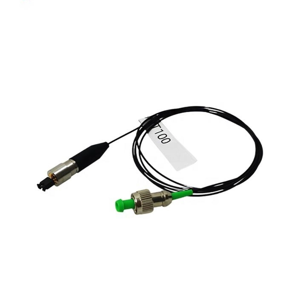
Fiber optic pigtails are short, single, or multi-strand pieces of optical fiber cables with a connector on one end and exposed fiber on the other end. They are typically used to terminate fiber optic cables and connect them to patch panels, equipment, or other termination points. Fiber pigtails are simple in appearance, yet essential in function. Despite this ubiquity, they remain a source of confusion for procurement teams and junior installers alike—especially when it comes to connector type selection, polish type, and the tradeoffs between mechanical. Fiber Optic Pigtails, also known as pigtailed fibers, consist of an optical fiber connector and a section of optical cable. Characterized by having an optical fiber connector on one end and a bare fiber end on the other, they are primarily used to connect optical transceivers or other optical. A Fiber Optic Pigtail Complete Guide: As per types, connectors, and applications. In such contemporary fiber optic communication systems, low-loss, and connectivities, which have reliability, are crucial for not only maintaining high-speed but also high-quality data transmission. It is usually suitable for field termination using a mechanical or fusion splicer. Compared with quick termination or epoxy and polish connections placed on the field.
[PDF]
