Cable Trays* — Max two 24 in. (610 mm) wide by max 6 in. (151 mm) deep open-ladder cable tray with channel-shaped side rails formed of 0. 54 mm) thick aluminum or min 0. In practice, cable tray dimensions are a system of interrelated measurements —width, depth, length, and material thickness—that directly affect cable fill compliance, heat dissipation, structural loading, and long-term expandability. From an engineering standpoint, cable tray dimensions are not. Perforated Cable Tray System expertly constructed from high-grade stainless steel, offering exceptional durability and resistance to corrosion. With side height 100mm. A properly designed and installed cable tray system will provide. Studs — Wall framing to consist of wood studs or channel shaped steel studs. Wood studs to consist of nom 2 by 4 in. Additional studs shall be used to completely frame. Best Size: Here, deep trays (75mm to 150mm) are used since power cables are typically thick and heavy. Data cables, such as your Wi-Fi or computer ones, are extremely sensitive. They do not get hot; however, they do not like to hang or sag. In case a data cable folds in an excessive manner, the. ect the minimum bend ra-dius for cables as they exit the bottom of the cable tray. A rung spacing of 6 to 9 inches (150 to 230 mm) is preferable when the cable tray cont d for instrumentation and control applications that require additional protec eferred to support and protect numerous small.
[PDF]
Mouser offers inventory, pricing, & datasheets for Bulk Transimpedance Amplifiers. The Relevance Inspector will open in the Coveo Administration Console. Transimpedance amplifiers parameters, data sheets, and design resources. Pricing (USD) Filter the results in the table by unit price based on your quantity. An instrumentation amplifier is a precision differential amplifier, typically built from three op amps, designed for accurate measurement of very small voltage differences in noisy environments. How it works: Two input buffers and a difference amplifier provide high input impedance and excellent. 1,Who we are ? Our headquarters is located in Shenzhen China with marketing experiences more than 16 years, The company has a professional R & D team, sales, procurement, logistics, warehousing, solutions, after-sales, to provide one-stop component services, in the field of industrial drones. Marvell's transimpedance amplifier (TIA) portfolio powers PAM4 and Coherent-based pluggable optical modules for high-speed cloud AI connectivity and long-haul optical links from 100G to 1. More data per optical symbol compared to older technologies Powering the fastest networks on. High-performance TIAs for next-generation optical receivers. Coherent's portfolio of high-speed transimpedance amplifiers (TIAs) delivers best-in-class signal integrity, high programmable gain, and exceptional power efficiency for optical interconnects ranging from 56Gbps to 224Gbps per channel.
[PDF]
In, a transimpedance amplifier (TIA) is a to converter, almost exclusively implemented with one or more (opamps). The TIA can be used to amplify the current output of, photo multiplier tubes,, and other (that are modeled well as a ) into a usable voltage.
[PDF]
A transimpedance amplifier (TIA) converts an input current into a proportional voltage, typically using an inverting op-amp with a feedback resistor (Rf). TIAs present a low-impedance input for current-output sensors such as photodiodes, preserving linear conversion and bandwidth. TIAs are conceptually simple: a feedback resistor (RF) across an operational amplifier (op amp) converts the current (I) to a voltage (VOUT). A transimpedance amplifier (TIA) converts a current to a voltage and is often used with current-based sensors like photodiodes. It's also a common building block that helps explain the performance and stability limits of many other op-amp circuits. Despite or because of their simple topologies, TIAs pose rigid tradeoffs among their gain, noise, and bandwidth (BW). The fundamental operation relies on an operational.
[PDF]

An Optical Splitter, also known as a beam splitter, is a passive optical device that divides a single input optical signal into two or more output signals. Conversely, it can also combine multiple signals into one. Knowing the difference between a splitter and an optical coupler helps you build better networks. You make your network work better when you pick the right device for each job. You can connect many users to one port with 1:n or 2:n splitters. By dividing a single optical signal from a central Optical Line Terminal (OLT) into multiple outputs for Optical Network Terminals (ONTs) at users' homes, splitters eliminate the need for dedicated fibers to each residence—slashing infrastructure costs while scaling network reach. This guide. In a Passive Optical Network (PON), a single optical fiber carries massive amounts of data using light. Signal Input: The fiber splitter receives the optical signal from the upstream network node and enters the splitter through the input fiber. Signal Distribution: Inside the splitter, according to the design structure and different. Splitters are passive optical devices that divide or combine optical signals, and they come in various types, including power splitters, uneven splitters, and wavelength-division multiplexing (WDM) splitters. Each type serves specific applications, enabling efficient use of optical infrastructure.
[PDF]
There are several different physical mechanisms that can be used to amplify a light signal, which correspond to the major types of optical amplifiers. In doped fiber amplifiers and bulk lasers, stimulated emission in the amplifier's gain medium causes amplification of incoming light.OverviewAn optical amplifier is a device that amplifies an directly, without the need to first convert it to an electrical signal. An optical amplifier may be thought of as a without an, or one in which. The principle of optical amplification was invented by on November 13, 1957. He filed US Patent US80453959A on April 6, 1959, titled "Light Amplifiers Employing Collisions to Produce Population Inversions".
[PDF]
Use this Raman amplifiers buying guide to compare major types, define selection criteria, and find suppliers: Professional purchasing of high-value photonics products is a substantial responsibility, where a structured decision-making process is essential. RP Photonics offers a lot of help: Get. The D7000 PDRA5014 is a high-power, low-noise raman fiber amplifier designed for distributed raman amplification, offering cost-effective solutions to extend the optical link power budget and significantly enhance OSNR. The PL-1000R enables long distance DWDM solutions and facilitates the transport of 100G/200G/400G and 800G wavelengths over. Our Raman amplifiers leverage internally developed, state-of-the-art 14xx pump lasers, internally developed intelligent algorithms for autonomous gain control, and robust safety features to deliver network-ready solutions. Key points of differentiation include market-leading metrics on power. Beautiful Complete Kaiser Optical Raman RXN2 Spectrometer Spectroscopy System! Get the best deals for Raman at eBay. We have a great online selection at the lowest prices with Fast & Free shipping on many items!. This guide addresses the technical and procurement needs of professionals seeking reliable Raman fiber amplifiers for long-haul optical transmission systems. Based on analysis of six leading suppliers from China—including Hangzhou Fullwell, Ningbo Youxin, Wentop Tech, Shenzhen Uonel, Xiamen.
[PDF]
An optical amplifier is a device that amplifies an optical signal directly, without the need to first convert it to an electrical signal. Optical amplifiers are used to create laser guide stars which provide feedback to the adaptive optics control systems which dynamically adjust the shape of the mirrors in the largest astronomical telescopes. An illustration of the effective gainis given below. Note the presence of a gain peak around 1530nm and. Optical amplifiers are a key component in modern optical communication and networking systems. While EDFAs dominate the C/ L bands (~1530–1600 nm) and Raman amplifiers enhance long-haul performance, other amplifier types extend coverage and functionality. In this comprehensive guide, we will explore the fundamentals and applications of optical amplifiers. An optical amplifier is a device that boosts the strength of an optical signal. Typical fiber cables experience a loss of about 0. 2dB per kilometer for 1. To compensate for these losses at regular.
[PDF]
For submarine applications, Raman amplification minimizes the number of underwater repeaters, enhancing reliability and cost-efficiency, while in terrestrial setups, it facilitates ultra-long-haul links over thousands of kms with reduced infrastructure needs.OverviewRaman amplification is a way of increasing the signal strength in an optical fiber. It is often used in a fiber that carries a signal for a long distance (such as in an undersea cable). Technically, it works by stimulating. • Poem, Eilon; Golenchenko, Artem; Davidson, Omri; Arenfrid, Or; Finkelstein, Ran; Firstenberg, Ofer (26 October 2020). • •.
[PDF]

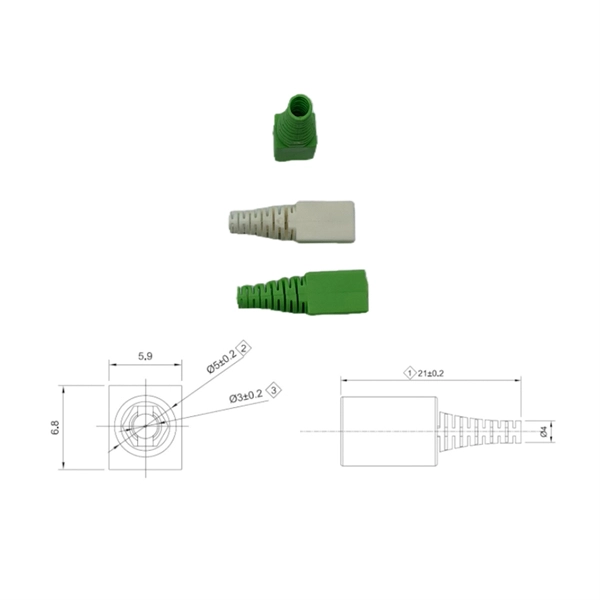
The LC optical fiber pigtail is designed with a push-pull mechanism, enabling easy installation and removal without compromising on performance. Executive Summary: A fiber optic pigtail is one of the most commonly specified yet least understood components in structured cabling. Get the wrong connector type, the wrong polish, or skip proper fusion splicing technique—and you're looking at elevated signal loss, increased back reflection, and a. Fiber pigtails are simple in appearance, yet essential in function. They are the bridge between fiber optic cables in the field and the equipment or patch panels that manage them. By combining factory-installed connectors with spliced bare fiber, pigtails ensure that network installers can create. Fiber optic network design refers to the specialized processes leading to a successful installation and operation of a fiber optic network. It includes first determining the type of communication system (s) which will be carried over the network, the geographic layout (premises, campus, outside. All Rights Reserved. fCONSTRUCTION QUALITY REQUIREMENTS FOR FTTP & SSP Work Orders This document provides Construction Technicians, Construction Managers, FTTP/SSP Vendors, and Inspectors with the essential information to ensure a quality build and to successfully pass an Outside Plant Inspection. These terminations must be of the right style, installed in a.
[PDF]
The 2025 Fiber Deployment Cost Annual Report, produced by the Fiber Broadband Association and Cartesian, provides the industry's most comprehensive benchmark of fiber build costs across the U. Drawing on data from operators and contractors in 38 states, the report shows that. Fiber optic network projects for industrial and oil and gas applications typically cost $15,000-50,000 per mile for aerial installation and $30,000-80,000 per mile for direct burial. Budgeting requires accounting for design, permitting, materials, labor, splicing, testing, and a 15-20% contingency. Buyers typically pay for fiber laying by combining material costs, labor time, and permitting plus trenching or aerial support fees. The main cost drivers are trench depth, fiber count and type (single-mode vs multi-mode), conduit requirements, and local permitting rules. This guide provides clear cost estimates, price ranges. Site Survey and Planning The first and most critical step in fiber optic network construction is the site survey—also known as a field survey. Engineers and planners assess the project area to determine the most efficient routes for the fiber optic installation. This information can help project leaders engage with providers and network operators in their area. This data is based on cost information.
[PDF]

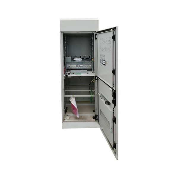
Whether you're an electrician or a DIY enthusiast, this tutorial will help you understand the fundamentals of wiring a distribution box for a residential setup. Hey, in this article we are going to see the Single Phase Distribution Box Wiring Diagram and Connection Procedure. A distribution board or distribution box is where the main power supply is distributed to multiple loads. And all the switching and protective devices are installed in the. The DB panel board controls the flow of electricity. It protects homes and industries from electrical hazards. It ensures that circuits are safe, organized, and easy to manage. A properly installed electrical distribution box is important for. Electrical systems power our homes, offices, and industrial facilities, but behind every reliable electrical setup lies a crucial component that often goes unnoticed: the distribution box. This essential piece of equipment serves as the nerve center of your electrical system, managing power flow. Welcome to our channel @Electricalgenius In this video, we'll take you through a detailed step-by-step guide on wiring a home distribution DB (Distribution Board) box. Distribution. Distribution box The system diagram usually shows the electrical connection and configuration inside the distribution box in a graphical way, including busbars, circuit breakers, fuses, load devices and other elements. In practical applications, the corresponding system diagram can be drawn.
[PDF]
For TDM-PON, a passive optical splitter is used in the optical distribution network. In the upstream direction, each ONU (optical network units) or ONT (optical network terminal) burst transmits for an assigned time-slot (multiplexed in the time domain). In this way, the OLT is receiving signals from only one ONU or ONT at any point in time. In the downstream direction, the OLT (usually) continuously transmits (or may burst transmit). ONUs or ONTs see their own data through the address labels embe.
[PDF]